What's New in Altium 365
Learn about the new features, enhancements, and important changes
introduced to the Altium 365 platform.
We're excited to announce the beta test of our new Design Review application for Altium 365, is now available for everyone to test. This new application accelerates your design reviews, tracks everyone’s feedback in real time, and prevents errors for higher-quality products.
Accelerate Your Electronics Design Process with our NEW Design Review Application
Design Review for Altium 365 offers development teams and engineering managers:
- Faster Reviews and Better Traceability: No more time wasted figuring out who hasn’t provided feedback. The status tracker gives you real-time visibility into which reviewers have given input and what still needs attention, making it easy to track progress and prepare for audits.
- Higher Quality Products: No more missed feedback. Capture 100% of stakeholder input and ensure it’s addressed, reducing the risk of last-minute redesigns, production errors, and costly product recalls.
Key Features
- Design Review Status Tracker: invite stakeholders and easily track when their review is completed. Use “voting” to see if they approve or reject the current design.
- Checklist templates and tracking: use included templates for various reviews or build your own and track progress on the Status Tracker.
- Comments and Tasks are in the design review for context: use comments and tasks as you normally would in Altium 365, but now you can track them by each design review.
- Compare Views tool: compare the current review with previous comments or releases to accelerate the review process.
- Design Review Report: once the review is approved or rejected, all review information is available in one place. Fields will be non-editable but available for future viewing for context and audit preparation.
Get Started with Design Review
Ready to streamline your electronics development process? Design Review is available for free to all Altium 365 users with the Organizational Security Package. When you open a project, you should see a navigation tab on the left side that says “Design Review BETA”.
If you don’t have our Organizational Security Package, you can still try our beta software by adding yourself to the beta test list. Go to the Design Review Try Now page and add your name to the list and you should get access within a few business days.
We hope you enjoy working with our new Design Review application!!

We encourage you to explore and test these new features and enhancements. If you need further information or want to share feedback, visit our documentation or reach out to us:
- Use the red-colored embedded feedback button in Altium 365
- Send an email to the Product Manager: EuJin Ooi.

- Learn more about the Design Review application
- Watch our Design Review webinar
- Design Review FAQs
- Design Review documentation
We're thrilled to announce the launch of Jira Integration for Altium 365, now available to all users. This powerful integration bridges the gap between electronics design and project management, streamlining workflows for engineering teams.
Enhance Your Electronics Design Process with Jira Integration
Jira Integration for Altium 365 connects your electronics design workflow directly to your Jira project management tool, offering:
- Real-Time Task Tracking: Keep your Altium 365 tasks and Jira issues in sync, ensuring up-to-date project status across both platforms.
- Seamless Collaboration: Create and link Jira issues directly from Altium Designer or Altium 365, with context-rich information for clearer communication.
- Enhance Visibility: Give project managers direct insight into design progress without leaving their familiar Jira environment.
Key Features
- Bi-Directional Synchronization: Tasks created or updated in either Altium 365 or Jira are automatically reflected in both systems.
- In-Context Task Management: Link Jira issues directly to specific design elements, providing clear context for engineering tasks.
- Secure Integration: Built with enterprise-grade security to protect your sensitive design data.
Get Started with Jira Integration
Ready to streamline your electronics design and project management workflow?
Jira Integration is available for free to all Altium 365 users with the Organizational Security Package.
New users can start a 14-day evaluation to experience the benefits firsthand.
Altium Designer 24.6 or later is required, along with an Altium 365 Workspace.
1. Go to your Altium 365 Workspace and go to -> Admin -> Apps -> Jira
2. Click on Connect if you have the Organizational Security Package or on Start Trial

- Learn more about the Jira Integration
- Watch our Jira Integration overview video
- Jira Integration FAQ
Elevate your electronics design process with Jira Integration for Altium 365. Start your evaluation today and experience seamless project management integration with your design workflow.
We are excited to announce that the Requirements & Systems Portal application has launched into the Altium 365 cloud platform for electronics design collaboration.
Requirements & Systems Portal is an AI powered requirements and systems engineering tool that ensures visibility and awareness of functional and system requirements from concept to manufacturing. It reduces costs, enhances quality, and mitigates risk in the product development process for electronics.
Reduce rework by connecting requirements to designs
Guarantee that electrical engineers have the latest values and current specifications and can view requirements in the context of schematics and PCB designs. Updates automatically propagate throughout your whole project.

Save time with automatic verifications
In Requirements & Systems Portal, requirements can be parameterized and important engineering data can live inside them. This allows for automatic and continuous verification as the project progresses.

Simplify complex projects with enhanced traceability
Manage requirements in a single place and link them to design elements and documentation, reducing the risk of errors and leading to faster, more predictable product delivery as your business grows.

Version control and requirement history
See the history of changes made to requirements and compare them across different versions. All changes—even automated verifications—are traced and versioned.

Get Started with Requirements & Systems Portal
Want to learn how connecting requirements directly to electronics designs can benefit your team? Get started by filling in the form on the Requirements and Systems Portal product page.
Quick Requirements & Systems Portal Demo

We’re thrilled to inform you about the latest updates to the Altium 365 BOM Portal, which includes the ability to manage and optimize multiple BOMs, visibility into parts usage, and autofill of alternate parts. These new features and improvements are designed to make your BOM management even more efficient, helping you streamline purchasing, reduce costs, and mitigate supply chain risks.
New Features
Consolidated BOM (Open Beta)
Combine multiple BOMs, adjust quantities, and optimize part selection. This feature allows you to consolidate similar parts manually, reducing the number of unique components, and potentially lowering costs with bulk ordering. Octopart users can export their optimized BOM or order parts directly from Octocart. Automated part consolidation suggestions are coming in the future!
Used Parts (Open Beta)
Gain a comprehensive overview of all components used across your projects. Monitor and optimize your parts usage, track part lifecycle, availability, and compliance, and streamline your supply chain management. This feature allows for manual optimization by identifying opportunities to consolidate similar components.
Autofill Alternates
Accelerate the process of adding alternates to your BOM with the new Autofill Alternates action. This feature works with both library-added alternates and those suggested by approved parts data providers (IHS, SE, Z2Data). The alternates from your library part choice list will be added by default.
Other Improvements
- Compare existing BOMs with new BOMs or any BOM in your workspace
- Specify your country/region in BOM settings to receive accurate SKU offers tailored to your location.
- App-level settings for BOM Portal:
- Assign users to the BOM Portal App and
- Define default settings for currency, country, favorite suppliers, and BOM checks
- BOM Portal UI adjustments:
- Increased height of the lines,
- Component preview,
- Freeze column action,
- Extra quantity support to add spare parts, and
- Item % column to show the percentage of BOM cost per line.
- Alternates are shown now in BOM comparisons
- Enhanced BOM Checks:
- Mismatch alerts between part number and BOM Item descriptions,
- Potential incompatibility of used alternates and
- Missing Part Number in PCL (part choice list)
- Improved MPN Resolution Logic:
- The system now uses the Name and Description columns to find and map the MPN if it’s not provided.
- Enhanced Revision ID Component Linking:
- Both Revision and Revision ID columns can now be used as Internal Part Numbers (IPN).

- Start your BOM Portal Evaluation here
- Learn more about BOM Portal
- Watch our on-demand BOM Portal Webinar
- Sign up for the upcoming webinar "Ensuring Electronic Component Traceability From Idea to Innovation"
We are excited to release a new Secure Collaboration tool, Altium 365 Organizational Security Package. A new package designed to give your IT security team advanced access controls and compliance tools to safeguard your data, while giving your design teams intuitive tools to manage your projects and teams.
Simple Tools to Manage Your Development Projects & Teams
Save time and get a better overview of your projects with our Jira integration. Organize your projects and teams as needed with multiple workspaces and unlimited data storage.
Easily Add Your Existing Access Controls & Compliance Tools
Strengthen access controls with IP whitelisting, group & workspace management, and your existing SSO. Gain real-time visibility into user activity and generate compliance reports through our SIEM Integration API.
| Capability | Description | Benefit |
|---|---|---|
| Multiple Workspaces | Supports creating and managing various workspaces, with admin controls over workspace creation. | Separate your projects into different workspaces so team members can focus on their specific tasks without being distracted by unrelated work. |
| Unlimited Data Storage | Ensures the team can store all projects and component libraries without space constraints or infrastructure worries. | Provides a cost-effective solution by allowing teams to store all projects without additional fees for increased storage capacity. |
| Jira Integration | Synchronize your Altium 365 electronics design process with your Jira cloud software. | Reduce operational costs of manual task updates and make better decisions by knowing the current status of your project. |
| Access to all Altium 365 apps | Your team has access to all the Altium 365 applications. | Your entire electronics development process starting with Requirements, Design, Supply Chain, and Manufacturing can be managed by Altium 365. |
| Capability | Description | Benefit |
| Multiple Workspaces | Supports the creation and management of multiple workspaces. | Compartmentalize design data across teams and workspaces, enabling auditability for compliance reporting and alerting. |
| Advanced Workspace Controls | Admins control the creation, file sharing, and uploading capabilities of new workspaces and Personal Spaces. | Manage the creation of new workspaces and Personal Spaces, enforcing security policies and ensuring consistency across the platform. |
| SSO, MFA, SCIM | SSO simplifies access with one set of credentials across multiple systems. Strengthen security over just passwords (Core Altium 365). MFA enhances security with multiple verification methods. SCIM open-standard protocol is used to simplify cloud identity and access management. | Easily manage and secure digital identities & control user access using your existing identity management tools Simplify compliance - companies can demonstrate data isn’t being misused |
| IP Whitelisting | Limit unauthorized access to your workspaces by only allowing specific IP addresses to access it. Add up to 100 IP rules. | Enhanced security by reducing the risk of unauthorized access of individual IP addresses, or ranges of IP addresses. |
| Group Management | Groups are collections of account users where group settings apply to all members. | Save time by setting up Groups with standardized access controls, licenses, and other settings based on roles or teams. You can also manage app and data access based on Groups. |
| Event Log | Includes detailed information for each event entry such as when it occurred, who invoked the event, and what object or User was affected. | Helps identify and mitigate security risk by offering visibility into actions taken within the system for audit and compliance purposes. |
| SIEM Integration API | Monitors and manages security events via API, providing analysis of security alerts from applications and network hardware, while exposing log data for SIEM with customer-managed configuration. | Use your existing SIEM and our API to enhance compliance, streamline auditing with comprehensive event tracking and reporting, and provide centralized visibility of security events across your organization. |

Learn more about the Altium 365 Organizational Security Package.
Learn more about the Altium 365 Jira Integration.
Watch a recording of our Organizational Security Package webinar: How to Protect Your IP While Accelerating Electronic Product Developement
Learn more about Altium 365 Information Security.
3D Fillet and Chamfer Translation
Feature: Automatic translation of fillets and chamfers on vertical PCB edges (Z-axis) in MCAD to the board sketch.
Benefit: Eliminates manual re-creation of fillets and chamfers for ECAD usage.
Smart Sketch Change Management
Feature: Retains unchanged elements in the board sketch during ECAD-to-MCAD updates.
Benefit: Reduces the need for manual restoration of dimensions and constraints after ECAD board shape changes.
Details: The "Smart Sketch Change" option allows for the disabling of complex scenarios.
Enhanced Pull Capabilities in MCAD (PRO/ENT/ADV only)
Feature: Ability to pull any previous pushes performed in ECAD.
Benefit: Easier retrieval of historical design iterations within MCAD.
Details: Updated automatic push policy: Automatic pushes from ECAD only occur on projects previously pulled into MCAD (since May 2024).

Try MCAD CoDesigner now.
Please visit the product page for more details about the MCAD CoDesigner functionality.
Dive deeper into the new features and improvements by exploring the complete release and details in our documentation.
Integrate your Altium 365 Workspace with an SIEM system using the SIEM API to capture and correlate security events, minimizing manual tasks and enhancing efficiency.
Real-Time Event Monitoring
With the SIEM API, you can transfer Events Log data to your SIEM system for compliance and auditing. This API, part of the Altium 365 Organizational Security Package, offers real-time monitoring and simplified troubleshooting.
Key Benefits of SIEM Integration
- Enhanced Compliance: Meet regulatory requirements by exporting audit logs effortlessly.
- Efficient Auditing: Streamline auditing with comprehensive event tracking and reporting.
- Centralized Visibility: Achieve a unified view of security events across your organization.
SIEM Example Use Case
Imagine a scenario where a company integrates Altium 365 with an SIEM solution. The SIEM detects an employee accessing sensitive project data outside of business hours from an unusual location exhibiting unusual behavior patterns. This triggers an alert, empowering an IT Analyst to evaluate the employee's behavior using contextual data related to their role, department, and access permissions.
Our Customer Success Managers will be available to assist customers with the integration. This feature is included in the Organizational Security Package. For more details on the package, please click here.
What is an IP Whitelist?
IP Whitelisting acts as a gatekeeper, ensuring that only traffic from trusted IP addresses can access your network. This is crucial for maintaining the integrity and security of your data.
Where is the IP Whitelisting Used?
IP Whitelisting is widely used in business-to-business communication scenarios, where APIs and services are private and intended to be accessed exclusively by specified entities. By implementing IP whitelists, organizations can establish secure communication channels with trusted partners, safeguarding against unauthorized access.
How Does it Work?
IP Whitelisting functions by filtering incoming traffic at the network's entry point, effectively blocking unwanted traffic before it can reach sensitive resources. This selective access minimizes resource interference and optimizes network performance by reducing unnecessary load and allowing access exclusively to pre-approved IP addresses. This feature is particularly designed for administrators who can manage and control access through the "Admin - Inbound Traffic" section.
Key Features:
- Restrict Access: Only IP addresses explicitly approved by administrators can access the workspace. By limiting access to approved IP addresses, IP Whitelisting reduces the attack surface and mitigates the risk of security breaches.
- Centralize Access Management: Administrators have the sole authority to add and manage IP addresses through the Altium 365 Admin Settings. This includes the ability to add both individual IPs and ranges of IPs. With exclusive control over IP Whitelisting, Altium 365 workspace admins can centrally manage and oversee access permissions, ensuring compliance with security protocols.
- Scalability and Maximum Capacity: IP Whitelisting offers a scalable solution for electronic development in Altium 365. It supports up to 100 approved IP addresses and provides ample capacity for organizations of varying sizes to manage access effectively.
- VPN Compatibility: If a VPN's IP address is whitelisted, users connecting through that VPN will gain access, ensuring that security is maintained without sacrificing flexibility.
Initial Setup:
For security purposes, administrators must first add their own IP address to the whitelist before adding others, ensuring that the setup process is controlled and secure from the start. Subsequently, they can add other necessary IPs, setting a robust foundation for controlled access. Watch our detailed walkthrough below:


Visit the website to explore more capabilities and learn more about it in our documentation.
🛒 Uninterrupted Procurement at Your Fingertips
- Direct Supplier Integration: Easily create a shopping cart on supported supplier websites like Mouser, Newark, Digi-Key, Online Components, and more on the way.
- Efficient BOM Management: Transform your BOM management experience by reducing manual steps.
How to Use It:
- Initiate Purchase: Click on the shopping cart icon in the managed BOM view of BOM Portal.
- Explore Suppliers: In the Octocart panel, view the list of supported suppliers used in your BOM's order list.
- Buy with Ease: Click 'Buy' or 'Buy All' to create a shopping cart on the supplier’s website.
Octocart ensures a smooth transition from BOM management to procurement.

👉 Get Started: Accelerate your procurement process with Octocart in Altium 365 BOM Portal and experience the convenience of integrated shopping and custom pricing.
Explore BOM Portal’s capabilities and learn about Custom Part Sources: List View Features, including Octocart and Custom Supplier Prices.
Tailored Pricing for Smarter Design Decisions
Strong supplier relationships are key to long-term business growth. This month, we focused on enabling deeper relationships with our customers and suppliers with Altium 365*. Now you can easily configure and view Custom Parts Provider Pricing for any BOM to scale your business and supplier relationships.
Real-Time Price Insights for Accurate Costing: View custom prices and special discounts from your suppliers directly in BOM Portal. With Custom Prices Support, you see real, discounted prices instead of generic ones during BOM and part selection, enabling more accurate part decision-making.
Consolidate Part Usage to Unlock Price Breaks: You can manage and collaborate on BOMs across projects to consolidate part usage to common preferred parts for bulk purchasing. No more switching between platforms and BOMs to view real prices, simplifying the design process and procurement.
How to Use It
- Set Up Supplier Accounts: Configure supplier accounts in Altium 365's Altium Part Provider page, using your username and password for authentication.
- Custom Pricing Integration: Once set up, custom pricing info from suppliers like Samtec, TTI, and Future Electronics appears alongside general pricing across all relevant Altium 365 features.
- Visible to All: While setup requires admin access, the feature and its benefits are visible to all users on the platform.
What to Expect
Immediate Access to Custom Prices: Get custom prices for used parts in Altium 365, including apps like BOM Portal.
*BOM Portal purchase is required to enable the secure connection to external part providers, but the pricing information is available on all apps connected to your Altium 365 Workspace.

👉 Get Started: Enhance your design process with tailored pricing information in Altium 365. Set up your supplier accounts today and make informed part decisions with ease.
Visit the to explore its capabilities and learn more about our documentation.
We are excited to unveil the Altium 365 BOM Portal, a new application designed to help engineers and procurement professionals reduce costly design respins and improve time to market with unmatched part data insights and collaboration features for all your electronic BOMs.
Proactive BOM Management & Collaboration
The Altium 365 BOM Portal bridges the gap between engineering and procurement, making their interaction more efficient for improved project efficiency. Centralizing supply chain and component lifecycle management on one platform enables swift, informed decision-making and reduces the effort in cross-departmental communications. This integration bolsters team coordination and accelerates the overall design-to-production process.
Unique Organizational Insights
The BOM Portal simplifies the import process, effortlessly integrating your existing BOM data from all your ECAD tools. Additionally, the portal allows for the creation of 'managed BOMs' from existing PCB projects, offering efficient and tailored BOM management for your organization. Beyond simple imports, it enriches BOM parts with additional data from leading providers like Octopart, IHS Markit, SiliconExpert*, and Z2Data* (coming soon), ensuring up-to-date specifications and supply chain details.
Data-Driven Supply Chain Risk Mitigation
The BOM Portal proactively monitors part supply chains and offers alerts on potential issues to preempt production disruptions, including availability and pricing across designated distributors. Make reliable supply chain decisions with ranked alternates for every component with part risk assessments and library health insights. Additionally, it incorporates “where-used” tracking for effective impact analysis and obsolescence management.
Spreadsheet Simplicity Meets Advanced Functionality
Combine the ease of spreadsheet-style management with the robustness of advanced document control. The capabilities of the BOM Portal extend to secure data sharing, easy data organization, and customizable BOM lifecycle states. The BOM Portal enhances BOM management efficiency, offering direct analysis and issue resolution from the interface. This feature-rich environment aligns with your design data, promoting an integrated and efficient approach to component management.

To learn more about the Altium 365 BOM Portal and get updates, please visit the following link: Altium 365 BOM Portal Product Page.
If you want to see our BOM Portal in action, watch our webinar recording.
Press Release
Blog: How Can I Make BOM Creation and Management Easier with a Cloud Solution?
The SiliconExpert integration opens access to many critical part properties; however, not all properties might be useful for every company. To help you focus on your key data points, we introduced the capability to control the default list of SiliconExpert properties that are visible in Altium tools. So when you request SiliconExpert information for specific parts, we will show only a specific dataset for each part. You can change these settings anytime and additional data will be available in the tool without additional quota usage if you already requested data for that part.
Admin settings (Admin -> Apps -> SiliconExpert) allow you to see your Part Quota limit, count, and remaining balance. More importantly, you can select settings visibility on the Workspace level to manage your part data request quota and parameter list. The Data Visibility Settings are split into parameter categories:
Checks Manager
The Checks Manager allows you to configure default checks for all BOMs, ensuring consistency and efficiency across your workflow.
Standardized Checks: Set uniform Check criteria and Report Level for all projects and BOMs, maintaining consistency and quality standards. Report Levels:
- Fatal Error
- Error
- Warning
- No Report
Efficiency Boost: Save time by avoiding repetitive setup for each new project or BOM.
Latest Parameter List - Jan 12, 2024
Miscellaneous
- Countries of Origin
- ECCN (Export Control Classification Number)
- HTSUSA (Harmonized Tariff Schedule of the United States)
- Last Check Date
- Schedule B (Export Schedule B Number)
- SE Grade (Specific Grade or Category)
- TARIC (Integrated Tariff of the European Communities)
- UNSPSC (United Nations Standard Products and Services Code)
Environmental - Specific Certifications
- Bisphenol A (BPA) Free
- Halogen Free
- Lead Free
- Green (Eco-friendly certification)
Environmental - Global Compliance
- California Proposition 65
- China RoHS Status
- EU SVHC List Version
- EURoHS
- Persistent Organic Pollutants (POPs)
- WEEE (Waste Electrical and Electronic Equipment Directive)
- ELV (End of Life Vehicle Directive)
Environmental - Substance Restrictions
- Global PFAS Assessment Status
- Inorganic Phosphorus Content
- ODC (Ozone Depleting Chemicals)
- PFOA (Perfluorooctanoic Acid)
- PFOS (EU Directive 2006/122/EC)
- Phthalates Content
- Rare Earth Element Information
- TSCA (Toxic Substances Control Act)
Environmental - RoHS and REACH Compliance
- RoHS Exemption
- RoHS Status
- RoHS Version
- REACH Contains SVHC
- REACH Restriction (Annex XVII)
- REACH SVHC Exceeds Threshold Limit
- REACH(SVHC) Information
General Compliance - Automotive Industry
- Automotive
- AEC Number
- AEC Qualified
General Compliance - Other Standards
- IEC 62474
- PPAP (Production Part Approval Process)
Overall Risk Assessment
- Overall Risk
- Overall Risk Percentage
Lifecycle Risk Information
- Estimated EOL Date (End of Life)
- Lifecycle
- Lifecycle Risk
- LTB Date (Last Time Buy)
- Obsolescence
- Part Lifecycle Stage
- YTEOL (Years-to-End-of-Life)
Multisourcing Risk
- Crosses Available Within Part Category
- Multi Sourcing Risk
Compliance Risk
- Conflict Mineral
- RoHS Risk
Inventory Risk
- Inventory Risk
- Other Sources
Military Specifications
- FSC (Federal Supply Classification)
- Military Part Number
- Military Specification
- Military Taxonomy
- NSN (National Stock Number)
- Vendor Part Number

Learn more about the SiliconExpert Integration or read more content.
Read the integration announcement.
Happy New Year! 🎉 We are thrilled to announce that the Altium 365 Assembly Assistant is now officially released and available for direct purchase through the Altium Store.
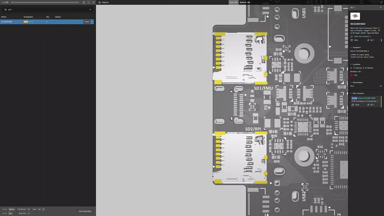
Fast and Accurate Manual Board Assembly
Manual PCB assembly often involves tedious cross-referencing between BOM and PCB printouts and navigating various CAD software. Assembly Assistant addresses these challenges by providing a web-based tool to simplify manual PCBA placement, improve efficiency, and minimize errors. Designed for ease and accuracy, the interface allows users to focus on precise assembly with an intuitive, user-friendly interface, eliminating the need for cumbersome paper printouts and complex CAD software navigation.
- Cut prototype/manual PCB assembly time by up to 50%.
- Combine BOM, PCB Viewer, and assembly instructions in one app.
- Avoid errors with cross-probing, linking BOM to 3D view for accurate orientation.
- Minimize costly production delays by ensuring accurate component placement.
- Design and BOM changes are instantly updated with the latest information.
Purchasing Assembly Assistant
With its availability in the Altium Store, you decide when to buy and start using it immediately.
Independent Licensing with Direct Purchase: Effective January 1st, 2024, Assembly Assistant has independent licensing and will not be included with Altium 365 or Altium Designer subscriptions. Purchase Assembly Assistant from the Altium Store.
License Terms: Access to Assembly Assistant is associated with a unique user (named user), identified by a unique email/username. Each license is valid for one year from the date of purchase.
Evaluate Before Purchase: As part of the free trial, you can assemble up to 10 boards at no cost, allowing you to experience the practical benefits of our Assembly Assistant firsthand.
Accessing Assembly Assistant
Assembly Assistant is available from the WIP view of a specific project, or from the Design Snapshot view of a project Release. Choose the Assembly Assistant option in the navigation tree to open the Assembly application in its interactive preview mode, and then at any time, invoke the assembly process mode from the Start Assembly button.

- For more details about the Assembly Assistant functionality, visit the Assembly Assistant Product page.
- To see Assembly Assistant in action, check out our webinar: 8x Faster Assembly per Board with Assembly Assistant
- Visit Assembly Assistant in an Altium 365 Workspace | User Manual | Documentation to learn more about this feature.
Altium 365 Web Viewer introduces a suite of new visualization shortcuts and features, enhancing the user experience for rigid-flex and standard design projects. These productivity improvements significantly enhance the design and review process, offering more intuitive and efficient ways to navigate and visualize electronic designs.
Key Enhancements
Rigid-Flex Design Interaction:
- Users can fold and unfold rigid-flex boards using the "5" hotkey, streamlining design manipulation.
3D View Customization:
- Flip the top/bottom view in 3D for any design using the "F" hotkey or the top/bottom buttons in the Objects panel.
- The ability to toggle the visibility of various objects in 2D and 3D views, including polygons, 3D objects, and connection lines.
Advanced Navigation Tools:
- Implementing “2” and “3” keyboard shortcuts for quick switching between PCB 2D and 3D views respectively.
- Double-clicking on an object selects the entire net, while single clicks offer iterative selection around the cursor.
Enhanced URL Context:
- The URL includes additional context such as window zoom/location, design/document view (e.g., SCH sheet 1 vs SCH sheet 2 vs PCB vs BOM), layers enabled (for PCB), and variant selection. This feature enables users to return to their exact previous view when reloading a page or sharing URLs.

This November, we introduced the Harness Wiring Component as the first step to reduce the need for third-party harness tools. This month, we present Altium 365 Web Viewer support for Harness Design Documents establishing a comprehensive, interactive browser environment for harness design collaboration with no tool installation or maintenance. All project stakeholders have a single space to review, inspect, and comment on the documents of harness and PCB designs (single and multi-board). Now team members can communicate design intent more effectively and reduce misunderstandings and delays.
Uploading and Creating Harness Projects
Navigate to your Workspace Projects tab and select New.
- Use Upload Project for existing projects.
- Use Create Project to select the
- Select Harness for your Project Template.
Navigate Document Structure and Properties:
Once you have created your project, four tabs are available for Wiring, Layout, BOM, and Draftsman documents. Harness documents listed under “Design > Source Documents” retain their Altium Designer order. You can share, comment, and inspect your harness design documents with the Properties panel to improve communication.
Navigating Harness Projects

For a complete overview of recent Viewer updates, visit the Altium forum here. Learn more about Harness Design with Altium Designer.
- Harness Design Overview Video
- Harness Design in Altium Designer
- Creating a Manufacturing Drawing for a Harness Design in Altium Designer
- Creating the Harness Layout Drawing in Altium Designer
- Defining the Harness Wiring Diagram in Altium Designer
- Creating a Harness Wiring Component for Use with Harness Design in Altium Designer
- Creating Harness Template Documents in Altium Designer
Support for non-CAD design files enriches collaboration by enabling online access to a complete set of project files, streamlining communication and decision-making, and making design reviews more comprehensive and efficient.
What are Non-CAD Project Files?
Non-CAD project files are essential components of a design project that aren't directly related to the CAD design. These include datasheets, design specifications, simulation results, and more in PDF, XLSX, CSV, DOCX, and ZIP formats.
Why This Feature?
Until now, the Altium 365 Web Viewer supported only Altium design files such as SCH/MBS, PCB/MBA, BOM, and Draftsman. However, users typically work with a broader range of project files that are available in Altium Designer, but not in the Web Viewer. This enhancement provides the foundation to track the complete project document spectrum within the Web Viewer, including both design and non-CAD files.
Accessing Non-CAD Project Files
- Open your project in the Altium 365 Web Viewer.
- Navigate to “Expand design >> other documents.”
- Select a PDF document to view or download it.
- For non-PDF documents, users can download them directly from the viewer.
Note: Only PDF files can be visualized directly in the Web Viewer, but other document types are available for download.

For a complete overview of recent Viewer updates, visit the Altium forum here or watch the update video at this link. Try it for yourself with the Altium 365 Guide.
The Harness Wiring Component integrates revision control for harness components, eliminating the need for manual copying and pasting of wire and cable designs. This enhancement is aimed at making the design process more efficient and error-free.
Our team is actively working to enhance the Harness Wiring Component feature, improving component usage tracking and implementing automatic updates for the latest cable revisions in Harness Wiring documents.

To learn how to create a Harness Wiring Component for use with Harness Design in Altium Designer, visit our documentation here. Engage with the community in our forum to exchange ideas with fellow users and connect with the Altium team here. We're here to answer your questions and support your needs.
The new feature is a valuable tool for engineers and designers who must share their designs with others or store and manage Gerber and ODB++ files. It can also be used to collaborate on legacy projects that use Gerber and ODB++ files.
To try the new feature, click the Upload button to your Altium 365 Workspace. Then, select the Gerber or ODB++ files you want to upload. Once the files are uploaded, you can view them, share them with others, and collaborate on them in real time.
Key Features:
Ability to Upload ODB++ and Gerbers: Altium allows users to upload ODB++ and Gerber manufacturing data directly into the workspace.
Manage Outputs in Altium 365 Workspace: Users can securely manage the outputs of current and legacy projects within the Altium 365 workspace. This likely streamlines project management and accessibility.
ODB++ Features: With uploaded ODB++ data, users can switch between layers, take 2D measurements, share their designs, and add comments. This makes it easier to collaborate and work on PCB designs.
Support for Gerber Formats: Altium supports both Gerber X2 and Gerber RS-274X formats and corresponding NC Drill files. This is crucial for PCB fabrication and ensures compatibility with different manufacturing processes.
Gerber Inspection and Management: For uploaded Gerber files, users can browse and inspect fabrication data, place and manage comments, toggle the visibility of layers, and perform measurements between placed datum points. This enhances the ability to review and fine-tune PCB designs.
Feedback and Support: We value your feedback! If you have any comments or suggestions or run into any issues while using this feature, please don't hesitate to let us know. Your input helps us improve Altium 365 Workspace.
Join the Discussion: Join the conversation on our forum to share your thoughts, ask questions, and connect with other users: Altium Forum.

To gain further insight into the process of uploading a Gerber or ODB++ Fileset, kindly click on the following link: Projects in an Altium 365 Workspace | Altium 365 Technical Documentation
New harness synchronization capability. This allows engineers to push the harness definition from ECAD to MCAD, where the mechanical engineer can define the cable routing through the enclosure and the connections to the printed circuit boards. The 3D harness definition can then be pushed back from MCAD to ECAD as part of the multi-board assembly. The physical length of wires, cables, and harness segments is assigned to the corresponding Harness entities in ECAD.
Multi-board assembly support for PTC Creo. This allows electrical and mechanical engineers to collaborate on the design of multi-board assemblies, including the synchronization of boards, mechanical enclosure, and 3D harness routing.
Other enhancements. These include improved processing of component models, working with workspace folders, and support for the new versions of MCAD software.

We recommend diving deeper into the new features and improvements of MCAD CoDesigner 3.5.0 by exploring the complete release and details in the New Altium MCAD CoDesigner.
Altium is excited to announce our new integration of SiliconExpert into Altium 365! This integration provides access to a wealth of component data directly within the Altium 365 WebViewer, the Manufacturer Part Search, and your ActiveBOM, enhancing your design process and decision-making capabilities.
Comprehensive Component Data
Explore data on over a billion electronic parts, ranging from the simplest resistors to the most complex ICs. With this integration, you gain direct access to extensive details sourced straight from manufacturers, ensuring the highest level of accuracy.
Risk Management
Mitigate design and production risks with comprehensive metrics, including YEOL date, multi-sourcing, and inventory risks, all accessible within Altium 365. This proactive risk management toolset fosters strategic decision-making, enhancing the reliability and longevity of your projects. With SiliconExpert's data, you can anticipate disruptions, effectively manage supply chain risks and safeguard the integrity of your designs.
Accurate and Reliable
Trust in the high-quality data driven by SiliconExpert's strict data integrity protocols. Regular updates guarantee that the component data you access is always the most recent, providing you with the most reliable information for your designs. Join countless engineers and manufacturers worldwide who trust and rely on SiliconExpert for their component data needs.
Experience the combined power of Altium 365 and SiliconExpert now, and design with confidence like never before!

To learn more about the SiliconExpert integration and get updates, please visit the following link: Design with Confidence: Altium 365 Meets SiliconExpert.
Altium has achieved CMMC Level 1 self-assessment, demonstrating our commitment to security. Users benefit from enhanced data protection, trusted relationships, access to SPRS scores, and CMMC 2.0 compliance. Organizations can leverage Altium 365 GovCloud to satisfy CMMC 2.0 requirements.
The SPRS score, the summary level score, helps identify a government contractor’s progress toward implementing the NIST SP 800-171 security controls.
We are actively working towards achieving Level 2 certification under CMMC 2.0. It is important to note that the CMMC Levels are cumulative, meaning that each level builds upon the requirements of the previous one..

For security and compliance information, visit our Trust Center. Altium 365 is designed to meet the requirements of defense and government projects. You can find the answer to your question and access the FAQ section by clicking here: My company works on defense or government projects. Can Altium 365 be used for such projects? Do you have corresponding certifications or compliance programs (NIST, ITAR, etc.)? Has your company achieved a Cybersecurity Maturity Model Certification (CMMC) of level 3 or higher?
We are grateful to our beta testers for their valuable feedback. Your insights and suggestions have helped us significantly improve the product, and we couldn't have done it without you.
Specifically, your feedback helped us to:
- The ability to reset the view by clicking outside of targeted objects.
- The ability to show a legend that describes the colors representing the added/removed/modified objects visually and in different list icons.
- The ability to filter the Differences list according to enabled layers:
The PCB Compare feature is valuable for PCB designers. It can be used to:
- Save time and money by identifying design differences between versions before prototyping, uncovering potential problems early on, and avoiding costly iterations.
- Help designers find differences between versions that are difficult to see with the naked eye.
- Track changes and ensure design consistency with version comparison during development.
- Pre-manufacturing verification to minimize production issues, ensuring a smoother manufacturing process.
Users can open the Project History or Releases page in the Altium 365 Web Viewer or Altium Designer to access the PCB Compare feature. From there, they can select two commits or releases to compare. Stay tuned for more updates and advancements as Altium continues to empower designers worldwide.

To learn how to invite other users to your Altium 365 workspace, please visit the following link: Design Data Comparisons in an Altium 365 Workspace | User Manual | Documentation
When you open a Multi-board project from the main Projects page, you will find tabbed view options for schematic (MBS) and board assembly (MBA) views.
The Altium 365 Web Viewer interface provides universal access to Multi-board projects through a web browser, allowing you to perform standard operations like opening, sharing, and renaming. You can navigate through child projects, explore their content, and delve into the properties of MBS entities, including Modules and Connections.
Every subproject can now be individually opened, allowing you to understand their unique contributions to the overall design. The Multi-board Tasks and Releases views utilize the Multi-board's subprojects, facilitating effortless tracking and managing the progress. The History view showcases a timeline of major events that have occurred chronologically.

For detailed instructions on how to utilize the Multi-board Design View in the Altium 365 workspace, we recommend visiting the following link: Web Viewer Functionality on the Altium 365 Platform | User Manual | Documentation
Altium 365 has introduced a new update that improves visibility and project management for external users. This update introduces the concept of "Guests" to identify and differentiate external users from workspace members.
Inviting guest users in Altium 365 can be useful in various scenarios, such as when working with external vendors or partners. An external user refers to any user not already a part of the workspace, typically someone from outside the company or organization. This update clarifies who belongs to the workspace members and who is an external user.
Workspace Administrators can easily manage guest users through the "Guests" tab on the Workspace Members page. This enhancement represents the first step in improving the management of guest users, and more capabilities will be added in the future.
It's important to note that inviting guest users is available for all subscription levels.

To learn how to invite other users to your Altium 365 workspace, please visit the following link: Managing Membership of Your Altium 365 Workspace | User Manual | Documentation
Your feedback matters to us, and we've been closely listening to your concerns about scheduled maintenance causing inconveniences when you have critical, last-minute changes to make before a deadline. We've taken decisive action to ensure a seamless experience on Altium 365.
We no longer require any downtime for Altium 365 to perform regular or weekly maintenance. This means that the platform is always available to you. Of course, from time to time, if there is a need for maintenance, we will announce it well in advance. We aim to provide a hassle-free experience while informing you about any necessary updates.
We have the Altium 365 status page at your disposal to ensure transparency and keep you fully informed. This dedicated page provides regular updates on the platform's status, including ongoing maintenance or any issues that may arise.

We encourage you to bookmark the status page (https://status.altium.com/) and subscribe for updates.
We are thrilled to announce a new feature in Altium 365 that empowers non-admin users to create invitation requests for new users to join the workspace. Previously, only workspace administrators could invite new users, limiting the flexibility to bring in additional workspace members.
In the current Altium 365 environment, non-admin users have had to rely on external means such as email to request workspace access, requiring them to know and contact the workspace admin directly. This disconnected process of inviting users and granting permissions often leads to inconvenience and inefficiency, as users must remember to request an invite and separately share project access.
With the introduction of the invitation flow for non-admins, regular users can now request workspace access for other users directly within Altium 365. This new functionality streamlines the invitation process, making onboarding new members to the workspace easier and more efficient.
This enhancement will greatly improve collaboration and project management within Altium 365, empowering regular users to actively participate in expanding the workspace. Try out the new invitation flow for non-admins today and experience its increased flexibility and convenience.

To learn how to invite other users to your Altium 365 workspace, please visit the following link: Inviting Other Users to Your Altium 365 Workspace | User Manual | Documentation
We're excited to announce the results of a study conducted by Forrester Research Consulting on the impact of the Altium 365® cloud-based electronics design collaboration platform. The findings reveal substantial significant efficiencies and effectiveness gains realized by organizations worldwide, establishing Altium 365 as a trusted platform that saves engineers hundreds of hours annually.
Proven Results
The Forrester Total Economic Impact™ study thoroughly analyzes Altium 365's economic and productivity impact. Forrester's researchers employed a rigorous methodology, considering both quantifiable benefits and the more nuanced influences of the platform on design processes and team collaborations.
The metrics uncovered by the study -- 159 hours saved per engineer annually and a 65% reduction in the need for alternative component sourcing -- are significant, demonstrating the platform's potent efficiency gains. We believe these numbers are strong evidence of Altium 365's impact and translate into concrete economic value for organizations. The saved hours represent cost savings and increased productive work time that can be redirected toward innovation and growth.
Furthermore, Forrester's study uncovers the platform's effectiveness and, for us, highlights how Altium 365 streamlines the production cycle. This streamlining is achieved by enhancing communication among team members, facilitating seamless access to files across global locations, and fostering a transparent supply chain that enables strategic, cost-effective purchasing decisions. This 360-degree improvement in the production cycle underscores Altium 365's capacity to redefine how organizations approach electronic design.
Experience the Power of Altium 365 Today
Altium 365 is committed to helping you develop better hardware products faster. As an all-in-one secure electronic design platform, Altium 365 offers automated workflows, allowing teams to confidently create, scale, and deliver secure electronic designs.
Join the thousands of satisfied clients and experience firsthand the efficiency, effectiveness, and component advantages offered by Altium 365. With our platform, you're not just designing electronics – you're transforming your entire process for the better. Get started today and unlock the full potential of Altium 365.

The powerful insights drawn from the Forrester Study highlight the transformative potential of Altium 365 in your organization. For more detailed insights, you can access the Forrester Study and a Forrester Infographic summarizing the key findings. Moreover, watch our webinar featuring Fabian Winkler, Product Marketing Manager at Altium 365, and Casey Sirotnak, Sr Consultant TEI Project Lead at Forrester.
Find more details here: https://www.altium.com/altium-365/forrester/impact-study
We are pleased to announce that Altium 365 has achieved SOC 2 Type 2 certification, demonstrating our dedication to upholding the highest standards of security, availability, processing integrity, confidentiality, and privacy.
The SOC 2 Type 2 certification builds upon the Type 1 audit we previously completed, which assessed the design of our controls (You can access the information about our SOC 2 Type 1 certification by visiting the following link: SOC 2 Type 1 Certification for Altium 365). In contrast, the Type 2 certification evaluates our controls' effectiveness and operational performance over time, ensuring consistency and reliability.
Moving forward, the achievement of SOC 2 Type 2 certification establishes a solid foundation for pursuing additional compliance certifications and audits based on the evolving needs of our customers. The reports on our certifications are available upon request under an NDA.

For more information about security and compliance topics, we encourage you to visit our Trust Center, where you can access detailed information about the certification and learn more about Altium's commitment to security, privacy, and compliance.
We are thrilled to introduce the Altium 365 Contractor Portal, an exciting new platform designed to connect you with trusted partners who are experts in electronic design and Altium 365. This portal offers you a secure and efficient space to connect with professionals specializing in Altium 365.
The Altium 365 Contractor Portal features a curated network of elite partners and contractors who have demonstrated exceptional skills and expertise in various areas of electronic design and Altium 365. We understand that finding the right partner is crucial to your success, so we will start with three carefully selected partners from around the globe to meet your needs.
Connect with the partner that best fits your needs and uncover the transformative capabilities of Altium 365. Whether you require basic assistance, expert guidance, tailored solutions, intricate design details, consulting services, or support in maximizing your projects, our partners are here to support you at every step.
Take advantage of this unique opportunity to save time and focus on what's important in your design capabilities. Visit the Altium 365 Contractor Portal today and connect with the perfect partner who will help you unlock the full potential of Altium 365. To learn more about the benefits of the Contractor Portal, please visit https://www.altium.com/altium-365/hire-experts
The new PLM Integration Configurator is a useful tool for product development teams using Altium 365. This tool allows users to configure and customize their PLM integration to best fit their team's needs.
The Configurator simplifies XML file management with a user-friendly interface, making data model integration from PLM and Altium 365 collaboration faster and more accessible. By integrating their PLM system with Altium 365, users can manage their entire product development process in one place, from design to manufacturing.
The new GUI in Altium 365 enables easy integration of data models and provides efficient dropdown menu functionality. Users can save time and increase productivity with in-place validation. In addition to the GUI vs. XML comparison, another valuable feature is the ability to pull data models from PLM and Altium directly into the UI. This allows users to configure their settings using dropdown fields instead of manually finding and editing configurations in text/XML format.
Please note that this feature is only available with the Enterprise Subscription of Altium Designer. To learn more about the benefits of Altium Designer Subscription Levels, please visit the Altium Designer Software Subscription Levels.

We also recommend visiting the following link to learn how to use the PLM Integration with Altium 365: PLM Integration with an Altium 365 Workspace | User Manual | Documentation
The Dictionaries feature is a real game-changer for maintaining the quality of your component library and minimizing errors and duplicates in parameter values. This feature promotes consistency and accuracy throughout the design process by establishing a set of allowed values for parameters.
To use the Dictionaries feature in Altium 365, you will need a PRO or Enterprise Subscription, and only authorized administrators can configure dictionaries through the web interface. To enable dictionaries in Altium 365, you must use component templates in Altium Designer.
Dictionaries in Altium 365 is a powerful tool that can help ensure the quality and accuracy of your component library. With dictionaries, you can define specific rules and constraints for different fields and parameters within your components, such as part numbers, pin names, and footprint names. By setting up dictionaries, you can ensure that all components added to your library adhere to these defined rules, helping to reduce errors and improve the quality of your library.

To discover how to access Dictionaries in Altium Designer, please refer to Exploring the Browser-based Interface of an Altium 365 Workspace | User Manual | Documentation
The Report information pane on the right will include full details of the selected entry, including the rule information, class and type, and the specific objects affected. To view it, click on DRC Reports or ERC Reports in the web browser to access their respective categories and sub-lists.
By utilizing the DRC/ERC reports in Altium 365 Web Viewer, managers and reviewers can save time and increase the accuracy of the design review process. The DRC/ERC report is included only when related errors have been detected.

To discover how to access DRC and ERC Reports in the Web Viewer, please refer to Web Viewer Functionality on the Altium 365 Platform | DRC and ERC Reports.
Altium 365 Personal has recently added support for ODB++ manufacturing data.
Once you upload an ODB++ package to your Personal Space, you can switch between layers, take 2D measurements, share your designs, and add comments.
As a registered user of Altium 365 (i.e., AltiumLive), your personal space is accessible only to you. You can access your personal space by logging in to Altium 365 and navigating to “My Personal Space.”


For more details on Altium 365 Personal Space, check out the following documentation: Altium 365 Personal Space | User Manual | Documentation
The newest release of MCAD CoDesigner 3.4.0 is finally here, and it comes packed with amazing features and improvements that will change how you work. With MCAD CoDesigner 3.4.0, you can connect native ECAD and MCAD design components to Siemens NX. This allows both engineers to work simultaneously on their respective components, which saves time and enhances collaboration.
Moreover, the new release includes advanced copper geometry support for Siemens NX, giving you even greater detail for your designs. You can now obtain precise definitions of shapes on every copper layer, ensuring accuracy and consistency. And that's not all! MCAD CoDesigner 3.4.0 also provides MCAD data management system support for specifying MCAD components as ECAD footprint parameters. This feature streamlines your design workflow and better supports the many-to-many relationships between components and footprints.

The advanced mode of rigid-flex design is another amazing feature of MCAD CoDesigner 3.4.0. This mode has moved out of beta and into public release, supporting SOLIDWORKS and PTC Creo. This means you can now design with even more flexibility and ease, making your job much easier.

Upgrade to MCAD CoDesigner 3.4.0 today and enjoy a more streamlined design process with improved collaboration, advanced copper geometry support, and data management system support.

We recommend diving deeper into the exciting new features and improvements of MCAD CoDesigner 3.4.0 by exploring the complete release and details in the New in Altium MCAD CoDesigner.
Introducing Altium 365 GovCloud - a dedicated region of the Altium 365 cloud platform designed for regulated companies and organizations handling sensitive data. Located on US soil and exclusively managed by US persons in the AWS GovCloud region, Altium 365 GovCloud allows organizations to ensure compliance with various US government regulations by choosing an Altium 365 workspace in the GovCloud region.
Participating in the United States defense supply chain, aerospace, energy, and telecommunications industries requires compliance with regulatory requirements such as ITAR and EAR. Altium 365 GovCloud can help organizations manage regulated product development, meet flow-down requirements as contractors and suppliers, maintain strict control over access to their intellectual property (IP), and reduce IT overhead.
Altium 365 GovCloud offers organizations all the features and advantages of the Altium 365 cloud platform, along with additional security measures customized for highly regulated industries.

To learn more about Altium 365 GovCloud, please visit our website and refer to our FAQ section for any questions or concerns. Join the community of users who have transformed their electronic design process with Altium 365.
Our primary objective is maintaining consistency in the project view between Altium Designer and Altium 365 Web Viewer. In the past, the default Altium Designer preferences used in the Altium 365 Web Viewer created discrepancies when non-default preferences were employed, leading to incorrect design displays during design reviews.
Specifically, we have addressed the following issues:
- Net overscores not being displayed when a single ‘\’ negation is present within the net label.
- Strings appearing to be rotated.
- Custom net colors not being visible.
To ensure that designs are displayed as intended, new preferences have been introduced in Altium 365 Web Viewer. The changes are as follows:
- Single ‘\’ negation ON ensures that single ‘\’ net overscores are shown.
- Display strings as rotated OFF ensures that strings always appear right-side-up.
- Net color override ON ensures that the custom net colors appear.
Through this, the design will appear in the web viewer exactly as the designer intended.
It's important to note that to see the changes, users must recommit/rerelease their projects to regenerate the view with the updated preferences. These updates were made in response to user feedback, and they will greatly enhance the overall viewing experience on the web viewer.

For more information on these new preferences, please refer to the following recommended content:
- Creating Circuit Connectivity in Your Schematics in Altium Designer for Single '\' Negation option on the Schematic.
- Why is my text upside down? | Altium Designer | Knowledge Base for Display Strings as rotated.
- Using Color to Highlight Nets on Schematics and PCB in Altium Designer for Net Color Override.
We are delighted to announce the release of a new feature that allows you to view multiple PCB documents in your project, including panel PCBs. This feature streamlines your design process, enabling you to access and collaborate on your entire PCB design in one central location.
We are in the open beta phase for this feature and are eager to hear your feedback. Your insights and suggestions will help us refine and improve the functionality to ensure the best possible user experience.
These new features make the web viewer more accessible for design collaboration and review without requiring Altium Designer/NEXUS installation or licensing. The features include:
- Access to all PCB documents through the design tree in the Altium 365 project Web Viewer.
- Ability to perform functions in PCB/3D views, such as cross-probing, commenting, searching, net navigation, measuring, accessing board info, and selecting variants.
- View embedded board array objects for panel PCBs.
- Option to measure panel PCBs between embedded board array objects or free/point-to-point measurements between fiducial holes.
- Ability to view multiple PCBs in design snapshots from Project History commits or Releases, in addition to the project's WIP view.

Please visit System-level Multi-board Design with Altium Designer to design multiple PCBs in Altium Designer.
Exciting news for Altium 365 users! The platform has enhanced its compare capabilities by adding PCB Compare operations between different commits/releases of managed projects. This latest feature, which complements Altium 365's existing compare capabilities for schematic, BOM, and Gerber files, provides users with comprehensive tools for reviewing and analyzing design changes.
Altium 365's compare capabilities are versatile and designed for different purposes, including design reviews, ensuring design compliance, and change tracking. PCB Compare can be accessed easily via Altium 365 Web Viewer's Project History, Releases page, or Altium Designer's Project History.
The PCB comparison feature can detect differences, such as board shape and board cutout changes, stackup changes, and net object modifications, including track, pad, via, and polygon. Non-net object modifications like track, pad, via, polygon, and keep out can also be detected, with some exceptions including graphics, 3D objects, OLE objects, and design views.
These changes are presented in a clear and concise 'Differences' pane, allowing easy navigation and cross-probing to the PCB compare view. In the PCB compare view, changes are color-coded and highlighted to give users a clear visual representation of the modifications. Red indicates removed items, green indicates added items, and yellow indicates modified items.

Please visit Design Data Comparisons in an Altium 365 Workspace | User Manual | Documentation to learn more about PCB Compare in Altium 365.
Altium Designer now offers the added capability to share project history reports with third-party entities in PDF format, while enabling users to save them as release artifacts for backup and internal auditing purposes.
This feature is in high demand among customers in heavily regulated industries, such as the medical, aerospace, and automotive industries, and it can serve as a reliable confirmation of implemented changes that can be seamlessly integrated into quality assurance processes.
Customers used to manually capture history page screenshots to achieve the desired functionality. To make this process easier and more streamlined, we have introduced a new capability that enables users to export project history reports in PDF format. The reports include general commit information, domain diff changes, and links to Commits and Releases. This makes it easier for users to share reports efficiently, saving time and effort. We aim to improve the user experience by simplifying the project history export process.
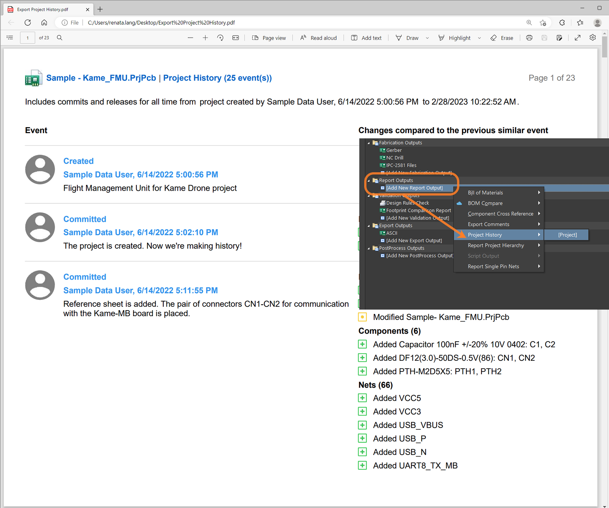
Key Features:
- Altium Designer's Project History Export allows exporting a project's history in PDF format.
- The report includes all the historical events from Project History, including MCAD events.
- General commit information, such as author, date, commit ID, commit message, tags, and domain diff changes, are also included.
- Users can choose to export the full history or only specific releases.
- The report includes links to Commits, Releases, and Comments, making it easier for users to navigate their project histories.
- This feature is available for subscribers at the PRO/Enterprise levels.

To learn more about Project History Export , please visit Creating a Project History Report | Documentation
Altium 365 Component Management provides the Part Choices functionality that shows supply information about the part you are interested in, including manufacturing lifecycle state, inventory, availability, and pricing.
The previous version of this functionality did not allow tracking changes to part choices (e.g., seeing what, when, and by whom it was modified), so this was a gap in the audit process that has been filled.
Revision-Controlled Part Choice
The revision-controlled part choice enforces special control over parts. Each set of modifications is captured in a snapshot of the item record called a revision. Each revision represents the state of that item at a particular instance in time. When a new revision is created, the previous revision of the item is permanently locked and cannot be changed. The functionality is available for Pro and Enterprise users.
Summary of What’s New in Part Choices
- You can decide whether a new revision will be created once the part choice is modified (by default, revision control is disabled).
- The component history shows an appropriate list of part choices for each revision.
- The compare components function was quickly upgraded to compare component changes in Part Choices.
Enabling Part Choice Revision Control
An administrator performs this through the Admin – Settings – Vault – Components page of the Workspace browser interface. To enable it, check the box “Part Choices Revision Control.” For more information, visit Exploring the Browser-based Interface of an Altium 365 Workspace.
A user must have Part Choice Management permission to manage part choices. To learn more about managing permissions, refer to the Setting Global Operation Permissions for a Workspace page.
New Operation Permissions
You can control who can edit Part Choices. Even if someone has the "edit" permission for Components, this does not mean they have permission to edit the Part Choices.
Part Choice Management Permission is available only at the Pro and Enterprise subscription levels. To learn more about Altium Designer subscription levels, please visit Altium Designer Software Subscription Levels.

To learn more about Part Choices, please visit Adding Supply Chain Information to a Component in Altium Designer.
The standalone Altium 365 Viewer provides free access to view and share your electronic designs and CAM (computer-aided manufacturing) data through your web browser. No downloads, no installations, and no registration are required.
Starting with this update, you can now view ODB++ files in Altium 365 Viewer along with other output CAM formats such as Gerber RS274x and Gerber X2 (with corresponding NC Drill (numeric control drill) data). Key features of this tool include the following:
Layers View
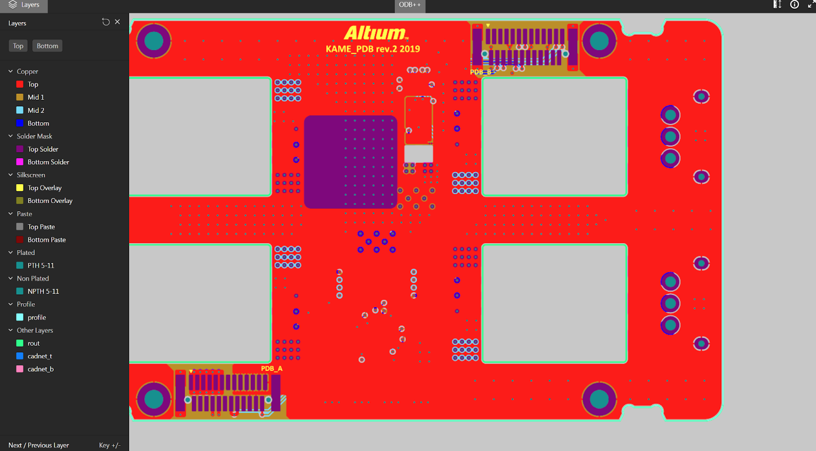
Right-click on the layer you want to see in the layers sidebar window. To select a single layer, click Only on the selected layer, highlighting it. You can also switch between the top and bottom layers.
2D Measurement

Take measurements directly in the viewer with the ability to measure freely between two points.
Change of Units of Measurement

You can change the units of the measurement tool (mm or mil).
Share the Design

Need to temporarily share a design with a colleague or manufacturer to get instant feedback? Click the Share button—the blue button at the top. Click Copy and your link will be copied to your clipboard, and you can share it. The link is only active for 48 hours after creation. The ability to share permanently through Altium 365 Personal Space is coming soon.

You can access the online Altium 365 Viewer at https://www.altium.com/viewer.

For more details on Altium 365 Viewer, check out the following documentation: Standalone Altium 365 Viewer | User Manual | Documentation.
With the latest update to task assignment notifications, project-level and workspace-level tasks will send notifications when events are assigned, or a user is mentioned in a task’s comment. The notifications ensure that people are notified and fully engaged even when they are not actively working on a given project.

Customizing your email notifications can help you stay up to date on important work, from new tasks you’re assigned to updates on tasks you’re following.
There are two levels of tasks in Altium 365: project level and workspace level.
- At the project level, Notification Settings can be configured based on preferences:
- All – get all notifications
- My (you are involved in) – Default – only when mentioned or assigned
- None – unsubscribe from all notifications
- For workspace-level tasks, notifications are always propagated.


For more details on Tasks, check out the following documentation: Working with Tasks in an Altium 365 Workspace.
Several tools have been used to run simulations based on your schematic and PCB layouts. When you run the simulations, you likely need to store the results where any team member can easily find them. The file sizes can vary depending on the simulation type, from small documents to massive binary files.
Simulation engineers do not always have access to Altium Designer, so there's no easier way to upload simulation results to Altium than doing it in the context of your project in the Altium 365 web browser interface.
This feature allows you to upload and attach any simulation file to an Altium 365 project. A strict association with the project makes the files easily accessible and traceable for any project collaborators or audit purposes.
Accessing the Simulation
Access to the Simulation page is gained from the management page for that project.
You can attach any file to a work-in-progress project on this page, edit the file name, and add a description.
Simulation File in a Release
You can attach simulation results to a specific release if the project has been released at least once.
Preview and Download
You can open files for preview (only supported for PDFs) or download the file.

Please visit Management of a Specific Project in an Altium 365 Workspace | Simulation to learn more about Simulation in Altium 365.
In Altium 365, you can add contextual comments to the entire project, including schematics, PCB design, bill of materials (BOM), and Gerber files. To see this comment in a schematic, for example, just go to a specific sheet and zoom in on a specific place where the comment is.
In the layers view mode, we preserve the location of the comment. There's no need to guess the comment's layer and position.
 For example, if you comment on a specific layer, Altium 365 will show you the exact layer you commented on and the comment's position on that layer. This is useful for understanding the specific issue.
You can also copy the comment link and paste it into any browser. The link will take you to the comment in the layer and its exact location in the document.

Please visit Commenting in Your Design to learn more about commenting in Altium 365.
When there are transitions of roles and responsibilities in your organization or other changes in the business, you may need to transfer ownership of a workspace or objects within it.
We have added an important update to Altium 365: the ability to transfer the ownership of an object (project, folder, or component) to another person. Changing the owner of a workspace was already possible in Altium 365.
Key Features of the Transfer of Ownership
The transfer of ownership feature enables you to do the following in Altium 365's web browser interface.
In Altium Designer, the following actions can be performed.
Will Transferring Project Ownership Reset Sharing Preferences?
No, transferring project ownership doesn’t reset sharing preferences, so all existing collaborators will still have access, regardless of the new owner's plan.
We are excited to announce four more productivity feature improvements in Altium 365 Web Viewer: Preserve View, Object Visibility, Net Selection, and Additional Keyboard Shortcuts.
1. Preserve View
The URLs now contain the full context of the design view: window zoom/location, design/document view (SCH vs. PCB vs. BOM vs ...), layers enabled (for PCB), and variant selection. This allows users to return to their previous view when reloading the page or provide specific context when sharing URLs with other users/people.
2. Object Visibility
This gives users the ability to toggle object visibility in 2D and 3D, including the visibility of polygons, 3D objects, and connection lines (or ratsnest).
3. Net Selection
This enables double-clicking on an object to select the entire net of that object. The ability to use subsequent single clicks to iteratively select objects around the cursor area remains.
4. Additional Keyboard Shortcuts
The 2 and 3 keys provide shortcuts for easily switching between PCB/3D views.
Altium 365 now allows the addition of screenshots to comments.
Sometimes a picture is worth more than words, and screenshots let you capture rework ideas, details from a component datasheet, manufacturer's website, or reference design to share with others or reference later. You can do it from a single place within Altium 365 without switching to emails or other apps to send or save your images.
When you place a comment in the design, you will read: "add others with @ or paste an image." A simple "Control + V" (Windows) or "Command + V" (Mac) or the right-click context menu to paste will add your screenshot to the comment. The screen will show you a thumbnail image of the screenshot in the comment dialogue, and then the screenshot will be added to this message. Anyone with access to the comment can click the thumbnail to see the full image embedded in the comment.
This new feature greatly increases the usefulness of Altium 365 feedback to teams during design reviews.
How to Get a Screenshot
The screenshot can be a full-size image or a section of an image of your screen taken with a capture application. For Windows, you can use Snipping Tool or Snip & Sketch to capture screenshots. The simplest way to take a screenshot in Windows 10 is to use the Print Screen button, but you can also use the shortcut "Windows + Shift + S." For Mac, press "Shift + Command + 3" to take a picture of the entire screen. To take a picture of part of the screen, press "Shift + Command + 4" and then drag the pointer to select an area.
It is now possible to store the naming schema used for released outputs as part of the project definition and template.
When preparing a project for release, you must ensure that the names of the output items are appropriate according to your internal rules. Altium Designer Project Releaser supports this flexible naming configuration.
However, the settings were previously stored on the computer used to specify them. When multiple people were working on the same project, other team members would see the default name settings if they tried to open the project release, not the one set by the user who defined it.
We have improved this capability, and the naming settings are now stored on the project level. If the user configures an item name at release, that name is saved on the server, and other users can see it correctly and use it.
To further facilitate reuse, you can create a project template based on your existing projects. Then, new projects from that template will follow the predefined item-naming conventions.
The Assembly Assistant helps reduce the time and increase the accuracy of the manual assembly of printed-circuit boards (prototypes or short runs). Engineers no longer need to flip through paper printouts or navigate CAD software while working on board assembly.
All the relevant design data, 2D and 3D board views, detailed BOM information, as well as the controls to track progress are brought together in one app specifically designed for manual assembly. The app is available through the web browser and can be accessed from any device without the need to install Altium Designer.
With the Assembly Assistant in Altium 365, you can employ the following features:
- Perform a visual inspection of the entire BOM and board before starting the assembly
- Check off each BOM entry sequentially as each component is mounted (mark as “done”) or bypass a BOM entry if needed
- Check the exact component location and orientation on the board
- Flip the board to view the top or bottom
- Have separate lists of components for the board's top and bottom sides
- Check full BOM information directly in the Assembly App for the selected component(s)
- Check multiple occurrences of the same component with grouping by component
- Track the total number of components placed
- Track elapsed time of the assembly process
- Reset the Assembly view to its initial state if the assembly process needs to be restarted
Note: This is an Open Beta feature, and we would love to hear from our users about how it could be improved further and any issues encountered.
How can you provide feedback?
Since the tool is in beta, your feedback is valuable to us. Feel free to share your ideas, comments, and suggestions through the following channels:
Through the Feedback button: Click the Feedback button on the right-hand side of the view. This will present a window in which you can rate your experience and include your feedback.
Through our forum: Provide us feedback through our Altium 365 forum on the following page: Web Viewer for Assemblers.

Visit Assembly Assistant in an Altium 365 Workspace | User Manual | Documentation to learn more about this feature.
Altium has released MCAD CoDesigner version 3.2.0.
The main highlight of this release is the new demo mode that allows new users of Altium MCAD CoDesigner to explore the features of this tool. The workflow runs simulated ECAD data, allowing users to explore autonomously without requiring an ECAD engineer to push the electrical data. To start the demo mode, follow the instructions in Demo Mode for CoDesigner.
Other enhancements include an Open in Web button on the MCAD Altium CoDesigner dashboard that opens the ECAD version of the project in your web browser; support for PTC Creo Version 9; an easy-to-use Fold/Unfold button for when you're working with rigid or flexible designs in PTC Creo or SOLIDWORKS; and improved component change details in Pull into MCAD, making it easier to confirm why a component parameter change was performed.
Here are the links for the Virtual Workflows:
In August 2022, we introduced you to net selection improvements in schematics with interactive navigation. As part of our ongoing initiative to enhance net selection, we have enabled you to instantly see and navigate a schematic containing a selected net thanks to a newly added zoom/selection feature.
When you select a net, you can zoom in and out of it, and your zoom is maintained even if you switch over to another document and then return. That way, you don't have to search for the net again.
We have also updated the Layers feature. Now, you can use the checkbox to set an active layer, which allows you to review specific layers while having other layers visible in the background.
You can use the checkbox functionality in the top and bottom views of the layer. The visual change is only made in the UI (View), so it will not impact the actual PCB layer.

Please visit Web Viewer Functionality on the Altium 365 Platform to learn more about Altium 365 Data View - PCB.
As we mentioned in a post in June, we have been working on adding more file comparison capabilities to Altium 365. In addition to the existing BOM Compare function, we have added a BOM Compare for local changes.
 It is now possible to compare local changes (uncommitted) to previous bills of materials on the server with Altium Designer. The compare option is available when you are about to save your changes (i.e., in Save to Server). Access this option anytime through the History & Version Control context menu.
 Note: This is an Open Beta feature, and we would love to hear from our users about any issues they encounter so that we can learn how to improve it further. Feel free to share your ideas, comments, and suggestions about BOM Compare for Local Changes in Altium 365 through our forum on the following page: Diff and Compare Operations in Altium Designer with Altium 365.

You can find more information about using BOM Compare in Altium 365 in the Altium 365 Getting Started Guide.
Draftsman is a drawing tool integrated into Altium Designer to create fabrication and assembly drawings.
With just a click, you can quickly view, download, comment, or create a task in a draftsman document directly in Altium 365 through any web browser and on any device.
How can you access the feature?
You can access draftsman documents in Altium 365 through work-in-progress (WIP), releases, and manufacturing views.
Draftsman in Altium Designer includes the following key features:
- Automated extraction of drawing data from the source PCB document
- Creation of multi-page documents
- Application of separate templates to each page of a document
- Automatic generation of drawings from customized templates
- A broad range of drawing views (Assembly view, Fabrication view, Section view, Drill Drawing view, Board Region view, etc.)
- Assembly views that include graphics generated from 3D models (without the requirement for special PCB layers)
- Support of assembly variants
Additional Features of Draftsman in Altium 365 Web Viewer:

You can find more information about using Draftsman in Altium 365 Web Viewer by visiting Draftsman in Altium 365 - Getting Started Guide.
What Is a Reuse Block in Altium?
A reuse block is a new entity (group of components or routed circuits) that can be placed to design and integrated with your projects in a couple of clicks. It contains a Schematic drawing and a PCB board. A block cannot be created without components or with an empty PCB part.

Design Reuse Panel
To access Reuse Block, select Design Reuse in Panels or View > Panel > Design Reuse in the top menu bar in Altium Designer.
The new Design Reuse panel provides access to reuse blocks and snippets. Snippets can be created in Workspace-based and local, whereas reuse blocks can only be created in Workspace-based settings. Let’s talk about the snippets later.

There is an option to see server-saved blocks and local and server-saved snippets. If not connected to Altium 365, you will only see local snippets; if a user is logged in, you see blocks and snippets in the server.

In the panel, you can add, see, sort, place, edit, and delete blocks:
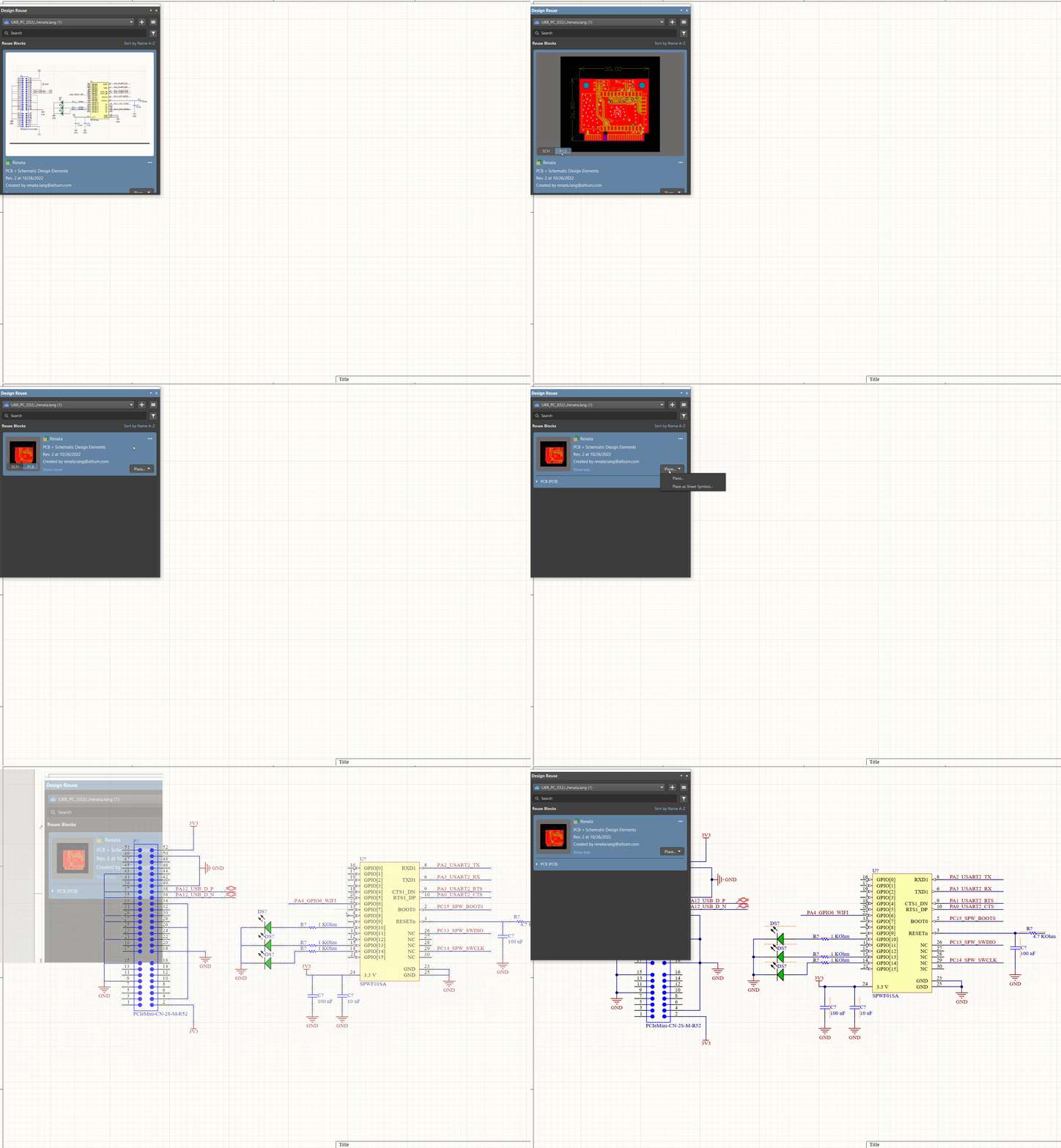
Snippets
In addition to reuse blocks, we added the ability to store snippets in Altium 365. To create a snippet, select a group of elements in a Schematic or PCB, and in the right-click menu, select Snippets:

Snippets can be saved either locally or in the Workspace:
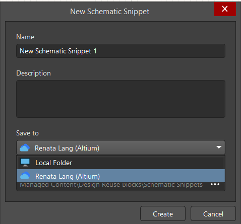
After creation, a snippet will appear in the Design Reuse panel:
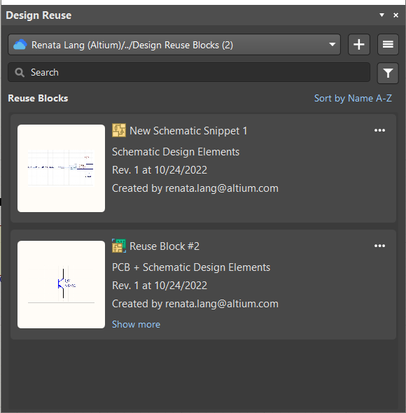

Please visit Creating Reuse Blocks to learn more about creating snippets and reusing blocks.
The Part Choices allows you to search, add, or remove company-ratified design parts for a specified component item.
Now, Workspace administrators can restrict permissions and authorize only explicit users and roles to change part choices. The Edit Operation Permissions dialog includes a new Part Choice Management entry.

Any user who does not have permission to manage part choices will be prevented from doing so when attempting to add or modify part choices for a component.
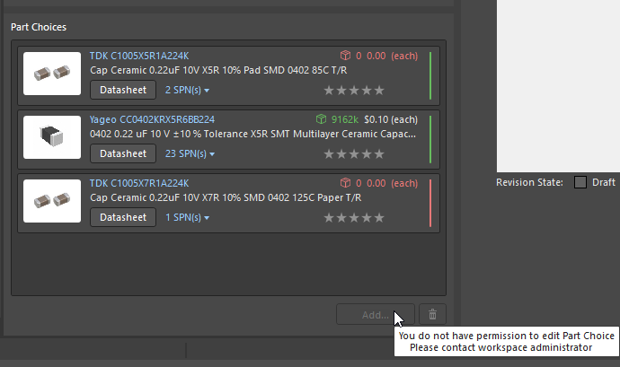
Part Choice Management Permission is available only with the Pro and Enterprise subscription levels. To learn more about Altium Designer subscription levels, please visit https://www.altium.com/altium-designer/subscription.

To learn more about Part Choice Management Permission in Altium Designer, see Part Choice Management Permissions | New in Altium Designer
Altium 365 allows users to tag specific points in a project's history. Tags help to navigate the project history and identify meaningful versions (such as design stage, review, and revision), see changes made in that version, open it for viewing, and share the link with others.
Note: The tagged project version marks all the comments with that tag, so it is easier to understand which comments come from which version. This feature is helpful when, for example, reviewing specific design versions.
Why Use Tags?
Think of tags as milestones or markers. They lead users or teams to a significant event. They can be used, for example:
- To mark the completion progress.
- To mark a significant achievement.
- Any other important tag.
Tagging makes it possible to search for (or go back in time to reference) specific events and open a specific snapshot without combining several comments.

Please visit Creating and Managing Project History Tags in the Altium 365 Getting Started Guide to learn more about this feature.
Every PCB project has a bill of materials (BOM). The design process involves multiple iterations and redesigns, and changes must remain traceable.
Finding differences between the two versions of BOM is one more way to reduce problems with BOM and inventory management. BOM Compare in Altium 365 is integrated and does not require external resources or plug-ins. This intuitive UI lets you quickly compare BOMs between commits or releases.
What are the advantages of using BOM Compare in Altium 365?
- BOM Compare expedites the comparison process by eliminating the need to update and compare BOMs manually. With a click of a button, you can compare BOM versions, saving time while reducing errors that occur with manual comparison or outside tools. Everything seamlessly integrates with Altium 365.
- Altium 365 can easily compare product design changes and updates during the design process.
- Altium's sophisticated part-searching capabilities are delivered through the Altium Parts Provider, which aggregates component information from the Octopart and Ciiva component portals. After using BOM compare, it is easier to check the suppliers and resources.
Key features:
- BOM Compare is integrated into Altium Designer tools, allowing you to generate various versions of the bill of materials directly from your layout. You can compare BOMs from each commit or release.
- Part-level attributes like Name, Description, Qty, Price, Manufacturer, and other attributes are automatically compared and highlighted if any changes exist.
- It contains approved part sources with supplier information and a link to Octopart/datasheet (Manufacturer Part Number).
- If you work with Excel, you can quickly export the BOM Compare file to CSV.
- The search bar makes it easy for users to find what they want on the list.
- The differences are highlighted and color-coded in the BOM grid. Supported modifications:
- New Items
- Updated Items
- Deleted Items

Visit BOM Compare in the Altium 365 Getting Started Guide to learn more about this feature.
The Library Health dashboard allows you to quickly identify parts in your library that have issues (including lifecycle issues for the parts and technical issues with data collection—e.g., invalid data, required fields with no values, undefined or duplicated parts, and other issues).
Before, it was impossible to act on the results in a batch way. Now, Altium 365 can act on issues by using a batch process. Selections are made using standard key combinations: Shift+click to select a range, Ctrl+click to select individual parts, or Ctrl+A to select everything. Edit these components in Altium Designer to resolve issues.
If you select “Open in Desktop App,” the component(s) will be opened in Altium Designer.
Process-based Workflow
A Workspace enabled by an active Altium Designer Enterprise subscription includes configurable process workflows to guide designers through the following everyday design processes:
- Requesting new parts for a PCB design
- Performing design reviews
- Creating new projects Publishing data to PLMs
A defined processes workflow is created and managed by an administrator of that Workspace.
Working with Tasks in Altium 365 Enterprise
In addition to benefiting from the Altium 365 Tasks, Enterprise-level subscribers have unique streamlined workflow task management, in which tasks can be linked to workflow processes. You can start the workflow activity from the project dashboard, not just the Activities or Projects pages.
There is now a single dashboard for all tasks (lightweight and workflow). Workflow tasks (design review, project creation, release, parts requests, component synchronization, etc.) are now exposed in the Tasks pane at the Workspace and Project levels:
Through the custom forms for workflow tasks, you can add details and assign people to work on tasks:
You can create different task types, which are all visually available on the dashboard:
You can directly trigger the workflow from tasks on the dashboard:
At the Project level, you can access the activity through a link added to the task:
The dashboard will show completed workflows as closed tasks. This ensures that the whole activity can be seen (with data and history). You can also hide the completed workflows by clicking “Show Less” in the Resolved column. Workflow tasks are grouped by title when all tasks within the group are closed, and the items in the Resolved category state are collapsed and moved to the bottom of the kanban.
Note: Workflow tasks cannot be moved between different states by dragging and dropping in the dashboard. These require explicit submission to move the workflow forward.
See more information about project files in Working with Projects in Altium Designer.
To warn you that duplicate files exist, you will be notified to ensure you are aware of this issue before you take corrective actions. We provide messages in several areas of the platform:
In the “Save to Server” dialog box in Altium Designer:

To see the name and location of those files, click “More Details”:

In the Messages panel in Altium Designer, when the project is opened:

In the project repository in Altium 365 Web Viewer:

Note: This is applied only to projects registered in Altium 365.

If you want to know why Altium Designer and Altium 365 Workspace are showing different design files for your project and how to fix this issue, access Altium 365 FAQs | User Manual | Documentation
By implementing actionable VCS status icons in Altium Designer, we provide a user interface exactly where you expect it. This makes VCS-specific actions light and easy to use, reducing the time required to perform them.
For example, if you face conflicting changes, you can simply click on the file status and see possible actions.

Once the file is out of date, you can quickly get a fresh version with a couple of clicks. See the example below:


To see the full list of icons, visit Version Control Status Icons, available in the Altium Designer documentation.
In Altium 365, you can open projects directly from Project History in the Workspace browser without needing an Altium Designer license.
Click the three-dot menu next to the 'Project Committed' and then Open Snapshot.
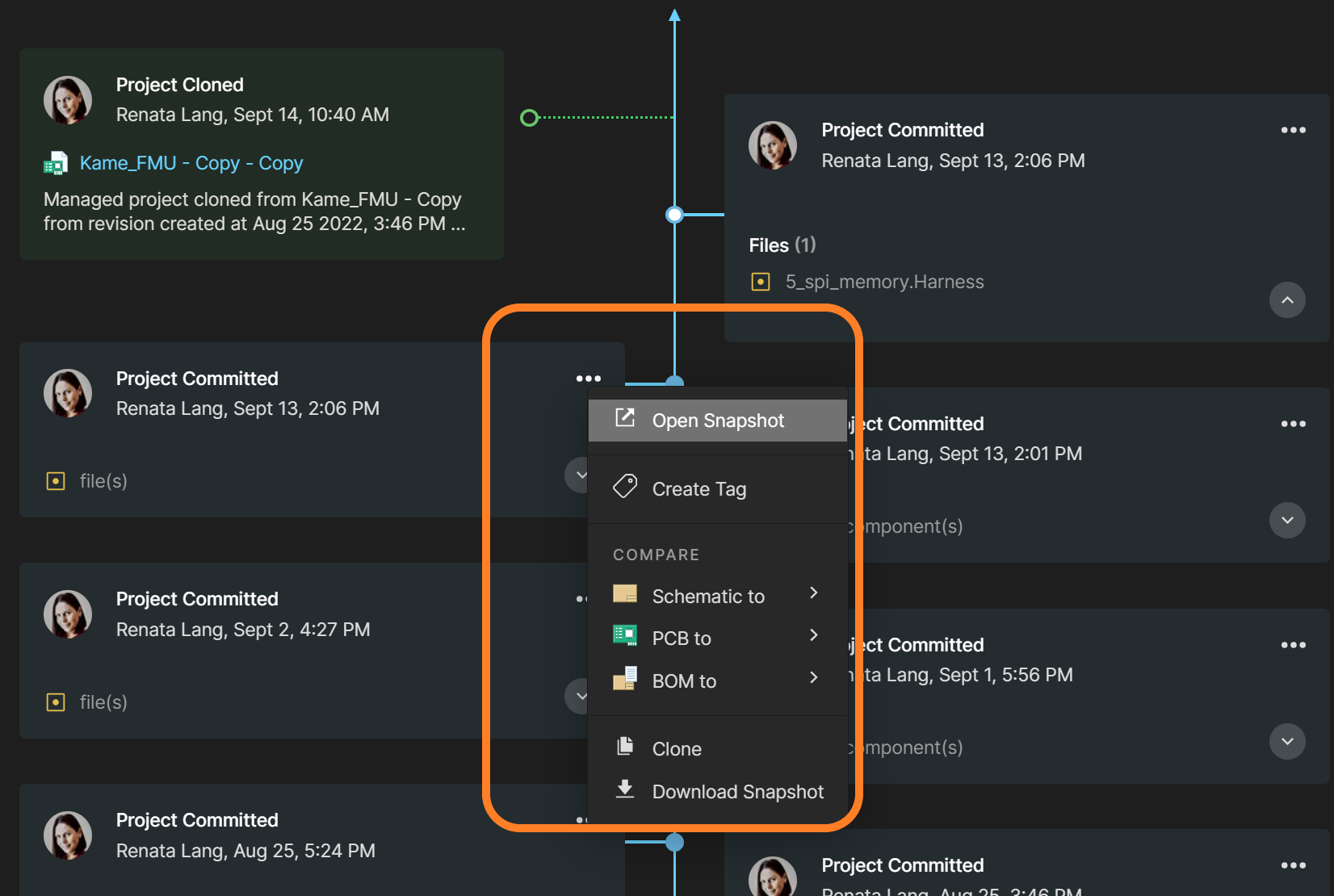
In addition to viewing the latest project version, which has been available for a long time, we have added the possibility of opening even the oldest versions. You can freely select any version from the project history tree, and you will access the entire design with the functionalities shown in the picture below.

If you would like to compare the differences between any two versions (commits or releases), you can use the Compare Function in Project History without the need to download any files.


To learn more about the Web Viewer Functionality on the Altium 365 Platform, refer to Web Viewer Features, available in Altium Designer Documentation.
There are many potential issues that can impact and cause delays for supply chains, such as fluctuating availability of components, hold-ups in customs, spikes in demand, and supply issues. Commenting in BOM was created to facilitate communication among stakeholders and users.
Note: This is an Open Beta feature, and we’d love to hear from our users on how it could be improved further and any issues encountered.
Commenting in a BOM allows users to communicate about changes or unexpected issues to reduce discrepancies and time spent on design changes. This feature is widely used in the following examples:
- To make suggestions for change to a specific part or component
- To highlight supply chain issues (e.g., delivery time, minimum order quantity (MOQ), changes to the product, price, availability, scheduling, inventory, product life cycle)
- To create information transparency for managers, buyers, sourcing teams, supply chain departments, procurement groups, and other users
- To reduce the number of communication channels
- To keep track of the BOM's comments for future reference in one place

These are the key features of commenting in BOM:
- Add comments to a specific BOM line
- Tag other users in the comments box using the @ function: the recipient will receive an email notification
- Assign a comment as a task to the person mentioned by selecting the Assign to checkbox
- Store all comments even if they are resolved or if the BOM line is deleted; you can still find all the history in the comments panel or when exporting comments
- People outside of your Workspace team—invited by you—can view and leave comments via a web-based application without an Altium Designer License


You can find more information about using this feature in Altium 365 by visiting Getting Started Guide - Commenting in your BOM.


To learn more about real-time conflict prevention, refer to Conflict Prevention, available in Altium Designer Documentation.
Altium has released a new simplified login for the web and registration user interface. You can still use direct or social login or Single Sign-On (SSO; if configured for your organization), but now in a more simplified and connected way.
Sign in now at https://365.altium.com/. Everything Altium in one account.

Note: This is an Open Beta feature, and we’d love to hear from our users on how it could be improved further and any issues encountered.
To streamline the early stages of a project, the Generic Components functionality is already available in Altium 365. Generic components can be quickly inserted into a project without the need to search for a manufacturer-specific part.
Generic components are intended to be placeholders that can be easily replaced later in the design process with a specific component. They can also be considered virtual or parametric components.
This feature is available with the Pro Subscription Plan only. To learn more about Altium Subscription Plans, please visit Altium Subscription Plans.

Please visit Creating Generic Components in Altium 365 Getting Started Guide to see the updated documentation.
Importing file-based libraries from your local computer or network drive to your Altium 365 workspace can be done using the Library Importer.
Altium’s Library Migrator was renamed Library Importer—the feature’s name was changed to conform more closely to the tool’s purpose.
Not only is its name new, but our team has also made several user experience improvements. We have updated the documentation to reflect this change. The list of updates includes:
- New, intuitive user interface.
- Along with the current method for accessing the Library Importer, the Library Importer can now be launched for an installed library listed on the Installed tab of the Advanced File-based Libraries dialog.
- Also, the Library Importer can be launched for an integrated library when opening.
- Validation now checks for empty Workspace folder paths, conflicting system parameters, and duplicate models.
We suggest that you start by importing an example library (included with the Altium Designer installation). Importing Libraries to Altium 365 explains how to complete the import process.

For the complete list of improvements, please visit New in Altium Designer | Altium Designer 22 User Manual | Documentation.
In Soft Locks [Conflict Prevention] in Altium 365, we discussed how you deal with file conflicts. We have updated the functionality to offer the possibility to compare the changes between the local version of the conflicted file and the one on the server.
Right-click the conflicting file and choose History & Version Control > Update the Whole Project. After resolving the conflict, the Merge File dialog will open, and you can click the Compare with Latest Commit button. This feature is intended for users to make decisions about adjustments to the project before committing them, saving time and resources.
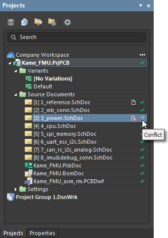

For more information about Local Compare, please refer to Diff and Compare Operations in Altium Designer.
To improve communication between ECAD and MCAD in such cases, we released Altium MCAD CoDesigner 3.0 with support for multi-board assemblies (the capability works in Beta mode and only for SOLIDWORKS for now; the corresponding changes to other MCADs are coming soon). To better understand how it works, this link provides a series of nine slides showing the details of how to work with MCAD CoDesigner in Multi-Boards.
In addition to that enhancement, Altium MCAD CoDesigner 3.0 includes support for Device Assembly in Autodesk Fusion 360, an automatic CoDesigner Push when you Save to Server, and the elimination of the display of “electrical” Keepouts and Rooms, removing visual information that is redundant for the mechanical engineer. With Altium MCAD CoDesigner 3.0, the support for Siemens NX has been released and is no longer in beta.
Define the default project folder path depending on teams, board functions, or product lines; e.g., create one project workflow with Projects/Lighting as the default folder, another with Projects/Audio as the default folder, and a third with Projects/Others as the default folder.
To set the default server folder for all subsequent new workflow processes, leave the field empty. The default path will be the one set under Settings/Vault/Projects.

Once you assign the default path, every new project you create will be saved in this default folder.

For more information about Process Workflow, please refer to Interactive Process Workflows.
Altium 365 has moved from a 32-bit service architecture to a 64-bit version. This update improves the speed, stability, and performance of Altium 365 cloud storage and version control capabilities, which will be particularly noticeable to users with big repositories and those who store large files on the platform.
It is important to validate proposed modification actions before executing them. Therefore, before committing, storing, or sharing the modifications with the team, you must ensure that no changes to the project are unexpected, no omission happened and only expected changes have occurred.
Comparing local changes (not committed) to previous versions or revisions of the projects on the server now is possible straight from Altium Designer. Schematics Compare is currently supported, but others (BOM & PCB) are under work.
Compare option is now available right when you are about to save changes (i.e., in Save to server) dialog and at any time before that from either Project History or Version Control context menu. When you click “Save to Server,” you can compare two schematics from a command in the dialog box before saving the project.


Before you save the project, go to Project -> History & Version Control to access Project History.

Project History is now extended with a new tile representing local changes (not yet saved to the server): you can see which documents were added, deleted, or modified. From this tile, it is also possible to perform comparison processes, such as between schematic documents.

If you choose to compare two schematics, the tool opens the Altium 365's Web Viewer interface, and the "Schematic Compare" view is displayed.

This is only the first step of the local changes update in Altium 365 Web Viewer. Over the coming weeks, more comparison capabilities will be announced on the “What’s New” website - stay tuned for more to come!

You can find more information about schematic compare in Altium 365 at Getting Started Guide | Schematic Compare in Altium 365 and about project history in Altium 365 at Getting Started Guide | Project History in Altium 365.
Altium recently released version 2.10.0 of the MCAD CoDesigner. MCAD CoDesigner now supports Teamcenter PLM when performing operations with PCB Assembly, PCB Part, and Components in Siemens NX. A new Advanced Geometry button has been added to the Fusion 360 Altium CoDesigner ribbon to simplify the working process for the copper and silkscreen layers. CircuitMaker can now also connect to Autodesk Fusion 360 through Altium CoDesigner.
Visit New in CoDesigner 2.10.0 for full release notes.
Note: This is an Open Beta feature, and we’d love to hear from our users on how it could be improved further and about any issues encountered.
Proper management of electronic parts enhances productivity, reduces costs, and can help mitigate risks associated with component availability.
Altium 365 provides a dashboard that allows you to gain insight into the library from multiple angles. This helps keep the library tidy and allows you to identify problematic parts (across all the components in the library or only the components in use). Some of the checks that are implemented include the following:
- Supply chain issues – Lack of sourcing, risky lifecycle states, and stock issues.
- Library maintenance – Use of outdated models or templates.
- Duplicates – Identification based on the component name or part choices keeps the library small.
By flagging duplicate entries, obsolete parts, unused data, and other critical issues, the Library Health Dashboard eliminates uncertainties and helps keep your library healthy and up-to-date.

Whether purchasing electronic parts or just selecting components for your project, you need up-to-date information about the components' health.

In the time it takes to finish a project, circumstances can change. With the Library Health Dashboard, you can conduct an in-depth analysis/investigation to find the source of any risks in your project and identify multiple issues quickly, such as duplicate components, outdated models, stock issues*, risky lifecycle states*, and outdated templates*.
In addition to reducing the risk of errors, manufacturers' names are presented so you can choose from those deemed reliable. You can view data sheets, descriptions, and inventory quantities in one central location on Altium 365.

*Some aspects of this feature are available only with the Pro and Enterprise Subscription Levels. To learn more about Altium Subscription Levels, please visit https://www.altium.com/altium-designer/subscription

You can find more information about Altium 365's Library Health dashboard at Getting Started Guide | Library Health Dashboard Altium 365
Conflicts can occur when multiple people work on the same project simultaneously. The user might not realize that they are not looking at the latest version of the documentation (as it was already modified by someone else), leading to problems later.
To address this issue, Altium features an intuitive graphical user interface that allows you to examine conflicts quickly and carefully:
- Altium 365 Version Control provides the design document's live status, which clearly shows the latest version, and highlights conflicts when they happen.
- Altium 365 Soft Locks proactively prevents conflicts from happening.
With Soft Locks, you can see when someone else is editing or viewing the same document you have opened, and it warns you and the other user(s) about conflicting changes. This allows for better coordination and communication among the team and avoids the need to merge files.
How do two people work on documents at the same time?
Real-time collaboration control for shared documents is available under the following conditions:
- The project is stored in an Altium 365 Workspace under the version control system (VCS).
- The collaborators are members signed into the Altium 365 Workspace.
- The project has been shared with all collaborators who have editing rights.
The overview below shows how this collaboration feature works in an already saved and shared project in the Altium 365 Workspace.
Collaborators Notification Bar
The Collaborator's Notification Bar appears automatically in the upper right corner of the Altium Designer when another user has opened the same document. Hover the cursor over the user profile icons within the bar to see the status of each user.

Editing Status
When someone is editing a document, you will see a pencil icon next to the user's profile. A document being edited by another user will have the user edit icon associated with its entry in the Projects Panel or a pencil paper icon if that document is currently open in the PCB Editor. The hover text will also indicate when multiple users are editing the shared document.

Suppose another user performed a local change more than two days ago but did not save this document back to the Altium 365 Workspace. In that case, the user edit icon in yellow will be associated with its entry in the Projects Panel.
The hover text of the icon will display an actual date of the last local change by another user.

Conflict Prevention
The system locks a document to the first user that edits it. This user’s soft lock remains associated with the file until this user finishes editing or is overruled by another user or an administrator.
In the example below, two users have opened the same schematic document. The user on the lower screen has edited the document, causing it to be soft locked to that user (User 1). This editing status is indicated to the other user (User 2 in the upper screen) via the Collaborators Notifications Bar. The Projects panel also displays the status.

If multiple people are in the document working at the same time, they can see each other in real-time. But, a warning will only be generated for the user who has the document locked (User 1) when the other user (User 2) tries to save their changes.
User 2, who has edited the locked document (upper screen), is presented with the option to cancel the changes (Revert My Edits) or overrule the lock (Ignore Lock) and retain their edits. Usually, the user abandons the change (Revert My Edits) and waits until User 1 has completed the current editing session.
However, suppose User 2 selects the Ignore Lock option. It means that more than one edited version of the document could be committed to the Workspace. The edits are potentially in conflict, as indicated by the red exclamation mark icon in the Projects panel for both users.
When more than one user is editing a document, its icon will change; if the document is saved. The document icon will change to a gray exclamation mark icon if the document is closed.

VCS Conflict
If users persist in committing their edits to the Workspace – overruling file locks and version control warnings – the different file versions will invoke a VCS Conflict, as indicated by an icon in the Projects panel. This can be resolved by adopting the latest version in the repository (i.e., the HEAD version) through an update from the Workspace. The conflicted file can also be maintained as a local-only version.
When this conflict occurs, users should collaborate to pick one version or another or manually merge the files.

Disabling the Soft Lock
You can disable the Edit Document Warning popup by unchecking the Enable Conflict Prevention Notifications under Project > Project Options in the main menu. This disables these notifications for users.

This feature is available only with the Pro and Enterprise Subscription Levels. To learn more about Altium Designer Subscription Levels, please visit Altium Designer Subscription Levels.

You can find more information on file version conflicts and their resolution in Using Version Control section.
The ActiveBOM is a powerful Altium Designer tool that provides real-time insight into the parts you need for your designs. It supports “early and often” monitoring to prevent manufacturing delays and setbacks.
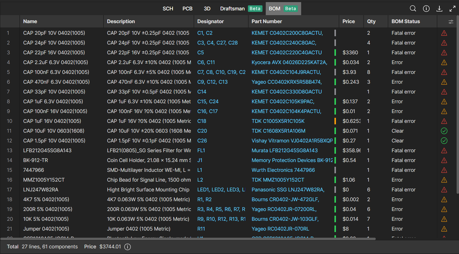
The increase in the adoption of ActiveBOM among our users in recent years shows that it is an excellent solution for solving supply chain issues. ActiveBOM enabled users to react rapidly to market changes, compete on time to market, satisfy demand quickly, and eliminate stock-outs.
The new Bill of Material (BOM) Viewer available in Altium 365 is a rich yet streamlined interface synchronized with Altium Designer's ActiveBOM. You can analyze BOM checks, view the components' parameters, check the component lifecycle, and create a customized BOM view relevant to you. Since BOM Viewer is accessible via the web browser, it can be easily shared with other teams (e.g., procurement) without requiring them to license and install Altium Designer.
The Properties panel is now updated to display the Parts Choices List (PCL) properties, allowing you to search, add, or remove company-ratified design components for a specified component item.
Column Visibility
Enable the table's column visibility toggle so users can hide or show table columns simultaneously. The default column visibility is synchronized with the ActiveBOM in the Altium Designer. Custom BOM rows, columns, and aliases are also supported (ActiveBOM required).

BOM Checks
This field actively checks the validity of the current data, which is illustrated through status icons. It also specifies the severity level associated with the violation check. The list of violations is managed in the ActiveBOM document. The icon is displayed in the last column of the BOM.
The search tool allows you to retrieve specific words. For example, you may want to find every capacitor or 0402 SMT size in the BOM.Search Tool

Cross Probe
Click the designator of any component to show where the component is located within the PCB in the schematics.

Part Choice List (PCL)
You can access the complete Part Choices List (PCL) with the new BOM view. The PCL defines the manufacturer parts; the suppliers are detected via the Altium Parts Provider in real-time.
The previous version of the details panel shared limited aspects of the component's information. In this new version, you can see the complete PCL, which means you can visualize the statuses of the models in the project (out of date/up to date) and have the ability to click and go straight to the manufacturer datasheet.

In addition to the described commands, you can copy any data from the component panel.

Visible for Work in Progress and Releases on Altium 365 Web Viewer
The BOM is available through the Releases and the Work In Progress interfaces in the Altium 365 Web Viewer, allowing you to view the feature from anywhere, simply accessing data through any standard web browser.

You can find more information about using BOM in Altium 365 by visiting the Altium 365 Documentation - Web Viewer Functionality on the Altium 365 Platform - Data View - BOM
Altium has just released version 2.9.0 of the MCAD CoDesigner. This version has the option to exclude small components when transferring from ECAD to MCAD. The arc behavior was improved, and the support for splines in board shape and cutouts was added. Now you can select a specific SOLIDWORKS configuration of a part on the board. We also introduced several improvements for Siemens NX.
Visit New in CoDesigner 2.9.0 for full release notes.
Altium 365 Web Viewer now includes a built-in PDF viewer that allows you to view PDF files in releases without an external PDF viewer application.
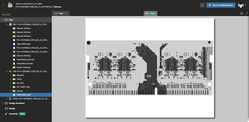
The key features of the PDF Viewer in Altium 365 are listed below:
- Load PDF files instantly
- Open and download the PDF files
- Easy page navigation
- Navigate with the Pan tool
- Zoom in/out using the mouse wheel
- Full-screen option
- Print PDF documents
- Display document titles
- Thumbnails: This allows users to preview all pages available in a PDF document.
- High-quality rendering: Ensure images stay sharp at all zoom levels.
- PDF document data: All the data are visually accessible, such as name, page count, file size, author, and creation date.

You can find more information about using PDF in Altium 365 Web Viewer by visiting the PDF in Web Viewer - Altium 365 Getting Started Guide.
With Altium 365, you can grant permission to teams or users based on the specific needs of a project. We have expanded Altium 365’s file-sharing setting, giving you more granular control over who can download source files and reshare projects with others.
Varying Degrees of Granularity
Altium 365 lets you set group or individual permissions so you can share a specific project with your team and provide editing or view-only permission.

Advanced Settings
Additional sharing permissions are available to the project owner and administrators in the Share dialog box. Use the Advanced Settings options to specify the re-sharing and download rights for users with whom the project is shared.
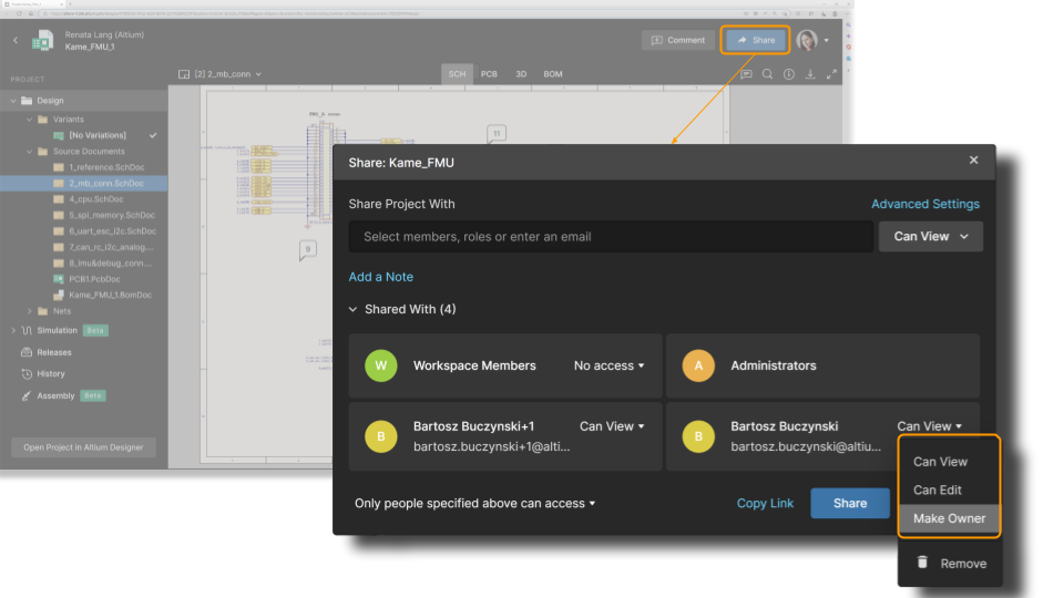
Sharing by Link
Altium 365 sends a notification to the users with whom your project is shared. Users can also copy and paste a link to the project and send it via chat or email so anyone with a link can view a project without having to download it. To generate a link to the design, click Copy Link and send it to users as needed. For requesting access and resharing, check Managing Access Requests in Altium 365.

Sharing to Organization
Companies can use access control functions to ensure view-only access within their organization—for all or specific projects inside the Workspace—without needing to invite people to the Workspace or directly share projects. Select “Anyone in can access” in the dropdown menu in the Share dialog box. This grants any user in the organization (with an AltiumLive account) access to view the project using the link. The design will also be visible in these users' “Shared with me” section.

Pending Approval
As an administrator or user with sharing permissions, you can individually review access requests for the project. When people ask for access, they see a message that an admin needs to approve their request. Once you approve a request, the user can see or edit the project based on the permissions you set.


You can find more information about using Granular Sharing in Altium 365 by visiting the Getting Started Guide - How to Control Access and Share Your Projects.
We are pleased to announce that Altium 365 is officially SOC 2 Type 1 certified.

The audit was performed by KPMG LLP, which included a review of Altium’s controls related to security, availability, processing integrity, confidentiality, and privacy, based on the Trust Services Criteria (TSC) of the American Institute of Certified Public Accountants (AICPA). The report ensures that the system is designed and implemented to meet the following criteria:
- Security. User entity data is protected from unauthorized disclosure and unauthorized access.
- Information Accuracy. User entity data is protected from unauthorized changes and safeguards information's accuracy and completeness.
- Regulatory Compliance. Altium has complied with policies, standards, and regulatory requirements relevant to the system.
Where can I get more information about security and compliance topics?
We recommend that you bookmark our Trust Center to find out more about SOC and information related to Altium’s security, privacy, and compliance.
What are the next steps?
To learn more about our SOC 2 Type 1 certification and the next steps, please access Announcing SOC 2 Type 1 Certification for Altium 365

Thus, users benefit from full data management capabilities in Altium 365 for their projects (e.g., domain, full project history, visual comparison of changes, and configuration of permissions in a single place) without losing change history (traceability).
Currently, the supported version control systems are Subversion (SVN) and Git.

You can find more information by visiting Migrating to Altium 365 from external version control systems.
The new 2.8.0 version of MCAD CoDesigner is out. MCAD CoDesigner now supports using a proxy with authentication in MCAD. PCB grid dots are no longer drawn for the "MCAD Coordinates" grid; this resolves the issue in which grid dots created difficulties with snapping on the PCB. This version also fixes a micro-deviation in coordinates that could occur when millimeter units were chosen on either the ECAD or the MCAD side. MCAD CoDesigner now supports the following symbols in the PCB filename: comma (,), single quote ('), and plus (+).
Visit "New in CoDesigner 2.8.0" for full release notes.
The Tasks feature takes design collaboration in Altium 365 to the next level. With Tasks, you never lose important action items and easily obtain a high-level view of the state of your project, all without leaving your design environment.
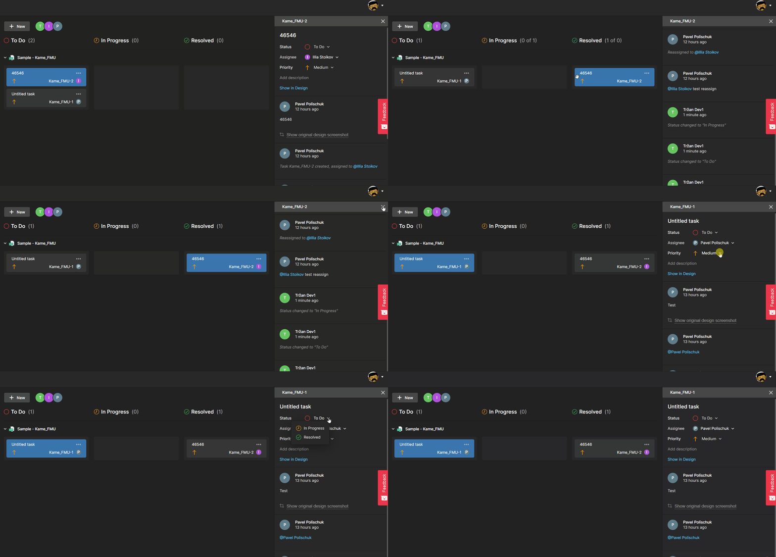
Feature highlights:
- Out-of-the-box task tracking without any additional configuration required.
- Tasks can be created and accessed from both Altium Designer and the Altium 365 web interface using comments or the dashboard (without an Altium Designer license). You can convert a design comment into a task with a single click.
- Tasks are part of the design process and always remain in the context of the project. They are accessible only to those with shared access to the design.
- In case you do not use any task tracker, you can use Tasks to streamline your task-tracking process. But even if you do, Altium 365’s Tasks will provide more context to the task.
This feature is available only with the Pro and Enterprise Subscription Levels. To learn more about Altium Designer Subscription Levels, please visit https://www.altium.com/altium-designer/subscription.

You can find more information on using Tasks in Altium 365 by visiting Getting Started Guide - Tasks.
You can add comments in the layer stackup of your board on Altium 365's web interface.
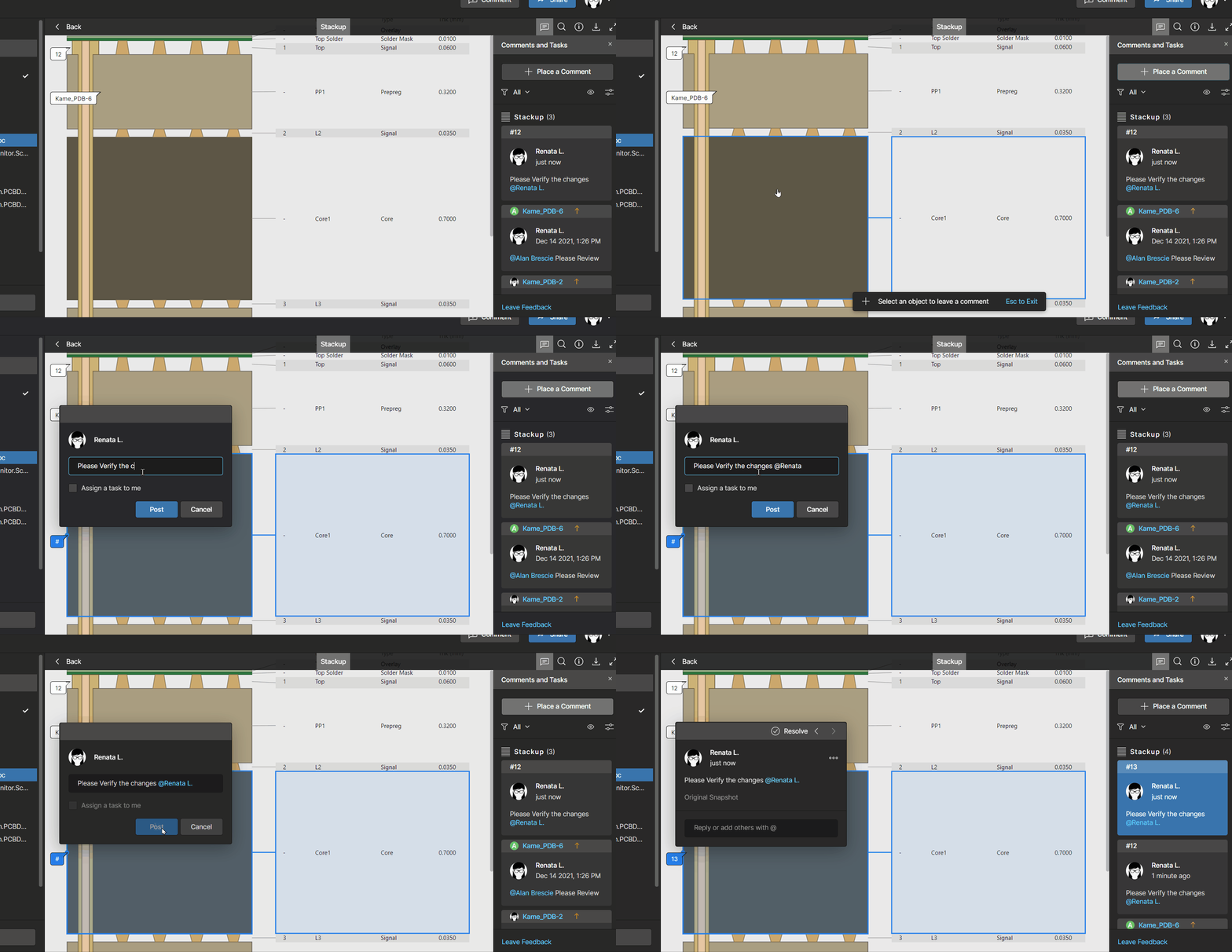
Our interactive commenting function has been expanded to the layer stackup. You can leave comments on specific layers or vias and keep all the communication in one place (please note that, at the moment, you can only leave comments in the web browser and not within Altium Designer).

You can find more information on how to use the Layer Stackup in Altium 365 by visiting the Getting Started Guide - Layer Stackup.
You can now access the layer stackup of your board on Altium 365's web interface.

Developing a layer stackup is a critical element of printed circuit board design. The ability to access and share stackup information via the web browser makes it easier to collaborate with different project stakeholders and manufacturers without the need for them to install and license Altium Designer.

You can find more information on how to use the Layer Stackup in Altium 365 by visiting the Getting Started Guide - Layer Stackup.
Now, with this update, the removed connectivity is displayed as a red dashed line between components or existing wires. To avoid visual clutter, the red dashed line is drawn as the shortest path between the previously connected objects.
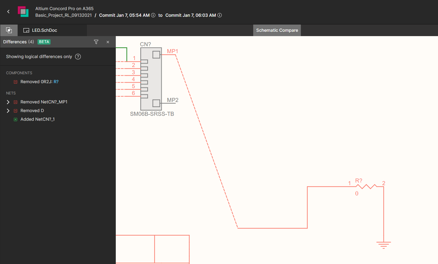
The feature’s second update relates to the footprint changes of a component. The differences panel shows when such changes are detected by comparison.


You can find more information on using Schematic Compare in Altium 365 by visiting the Getting Started User Guide - Schematic Compare.
Downloading the entire comment history in detail is sometimes necessary for historical, legal, or auditing purposes. Altium 365 enables the quick and easy export of the entire project's comment history as a single PDF file.

This file can be created as an ad-hoc report using Reports -> Export Comments from the top menu in Altium Designer or included in the release package as part of the output job configuration.

Please access our online documentation for detailed information on this feature: Export Comments in Altium 365. If you want to learn more about commenting in Altium 365, please visit Commenting in your Design.

A single sign-on solution simplifies username and password management. You no longer have to keep track of various credentials—simply remember a single, more complex password. SSO allows you to access MCAD CoDesigner much faster.
For more updates on MCAD CoDesigner, please visit: New in CoDesigner
The Trust Center Knowledge Base
The Altium Trust Center Knowledge Base is a self-service library of our users’ most frequently asked questions about security, reliability, and compliance. If you can’t find the information you are looking for, please send your question to us, and we will add it to the knowledge base.

Note: This is an Open Beta feature, and we'd love to hear from our users on how it could be improved further and about any issues encountered.
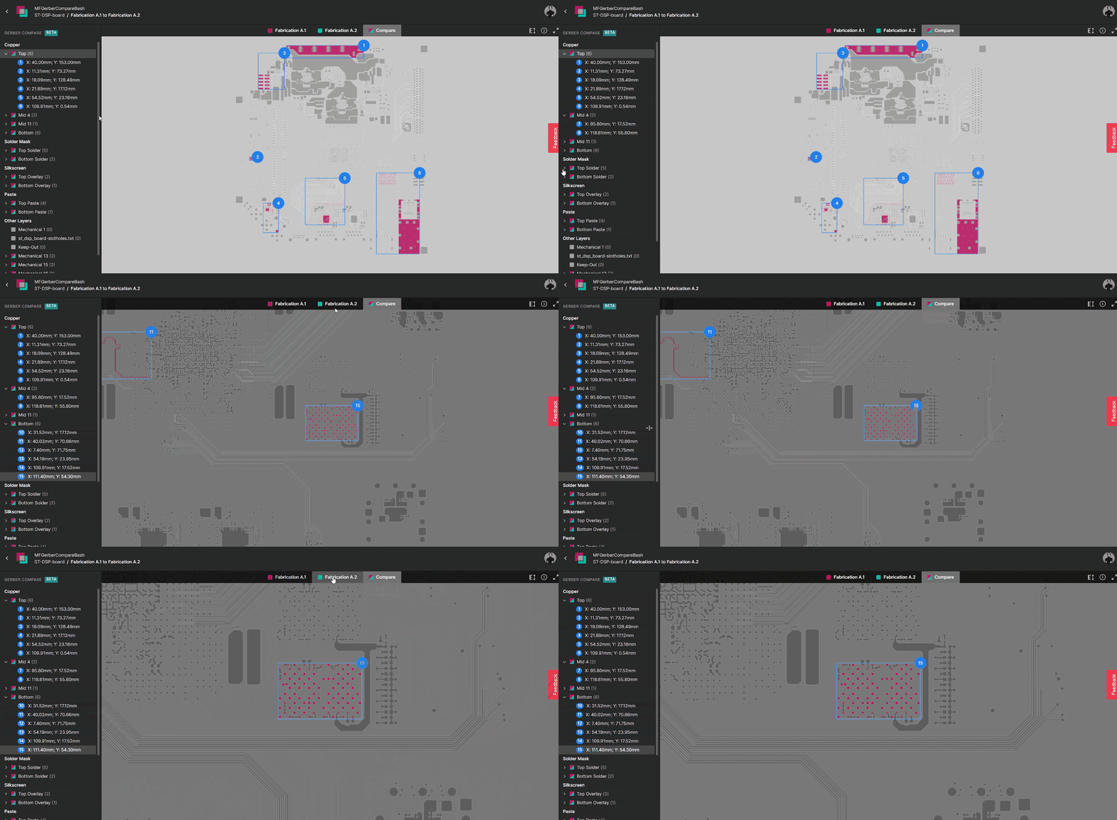
How can you see the differences between two Gerber files?
1. Differences in a macro-level view
Changes are organized into groups with explicit identification on the screen that corresponds to areas of the board that were changed. Changes are displayed per layer.
A. Clicking on a group will display a compare view that highlights any differences between the two revisions. As you can see, each group has a number, which is the number of differences.
B. You can switch quickly between layers on the side panel (see Fig. 3 - Quick view of changes).
C. When you switch between different layers and revisions, the location and zoom settings are preserved.

2. Easy navigation between revisions
You can quickly switch between the old revision, the new revision (that features a full Gerber viewer), and the comparison screen, which shows the difference between the two Gerber files.

3. Quick view of layers that have changed
You don’t need to know which specific layer was modified beforehand—the software will check and display it on the screen with the number of changed areas.
All layers that are not modified appear in gray.

4. Color Coding of Changes
Gerber Compare has the ability to perform a graphical comparison; areas that have not been modified are gray. Red indicates the changes in the previous revision of the Gerber file.

5. Cross-probing capability
This feature also includes bi-directional cross-probing capability between the change on the side panel and the detail. Once you identify a specific change of interest, you can highlight relevant information about it.

6. Distance Measurement
The Distance Measurement tool reports the point-to-point distance, the X (horizontal) distance, and the Y (vertical) distance in both metric (mm) and imperial (mil) units. The Measurements panel provides quick access to these measurements. Its primary function is to help you compute the exact measurements to use in the PCB manufacturing process.

How can you access Gerber Compare?
- The Releases tab in Altium 365: compare Gerber data between releases or against a locally generated file set.
- Project Releaser in Altium Designer: compare with previous releases as part of output preview steps.
How can you provide feedback?
Since the tool is in beta, your feedback is valuable to us. Feel free to share your ideas, comments, and suggestions about Gerber Compare through the following channels:

- Click the Feedback button located at the right-hand side of the view. A window will be presented with which to rate your experience (star rating), and then to elaborate, with the option to select an element of the interface to include with your feedback. Please supply your email address if you are willing to be contacted by Altium about your feedback.
- Through our forum: Altium 365 feature introduction: Gerber Compare (Beta).

You can find more information on using Gerber Compare in Altium 365 by visiting Getting Started Guide - Gerber Compare.
Sharing access to projects in an Altium 365 workspace can be restricted to preserve data privacy. In the past, users without sharing permissions needed to contact someone with sharing permissions and request access to others. To make this process more manageable but still preserve security properties, we've implemented “Requesting access to a project for someone else”.
If you are not familiar with the sharing controls in Altium 365, we suggest you check the guide: Allowing Access to Your Project: Design Collaboration.
Requesting Access for Others
You will know that you don’t have access to share projects because a sharing dialog box will display this information when you click the share button: “You do not have permissions to share this project. Supply the emails of people requiring access below. An administrator for the project will act on this request.”
Select “Add a Note” if you want to add a message explaining why this request is needed (optional).

Requesting Project Access
If you receive a link to an Altium 365 project and don't have access to it, the message “You need access to the project” will show up, and you can request access with an optional message for the owner of the project:

Access Request Notification
Once access is requested, anyone who can share the project receives a notification email.

In the email, “Open sharing settings” is a clickable link so that the admin can go directly to the sharing and access controls. All your pending requests will be visible there.
After accepting the request, an email notification is sent automatically to the accepted user.

For more information on the subject, you can read the Altium 365 User Guide: Sharing a Design in Altium 365
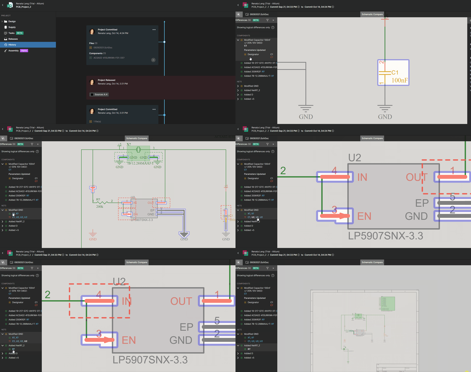
How can you see the differences between the schematics?
1. Compact overview of the differences
With built-in Schematic Compare, you can easily visually compare changes between schematics. This automated process allows you to quickly and accurately analyze the differences and review each change individually. This representation refers to the latest version of the schematic data but with the color code of changes compared to the chosen older schematic.
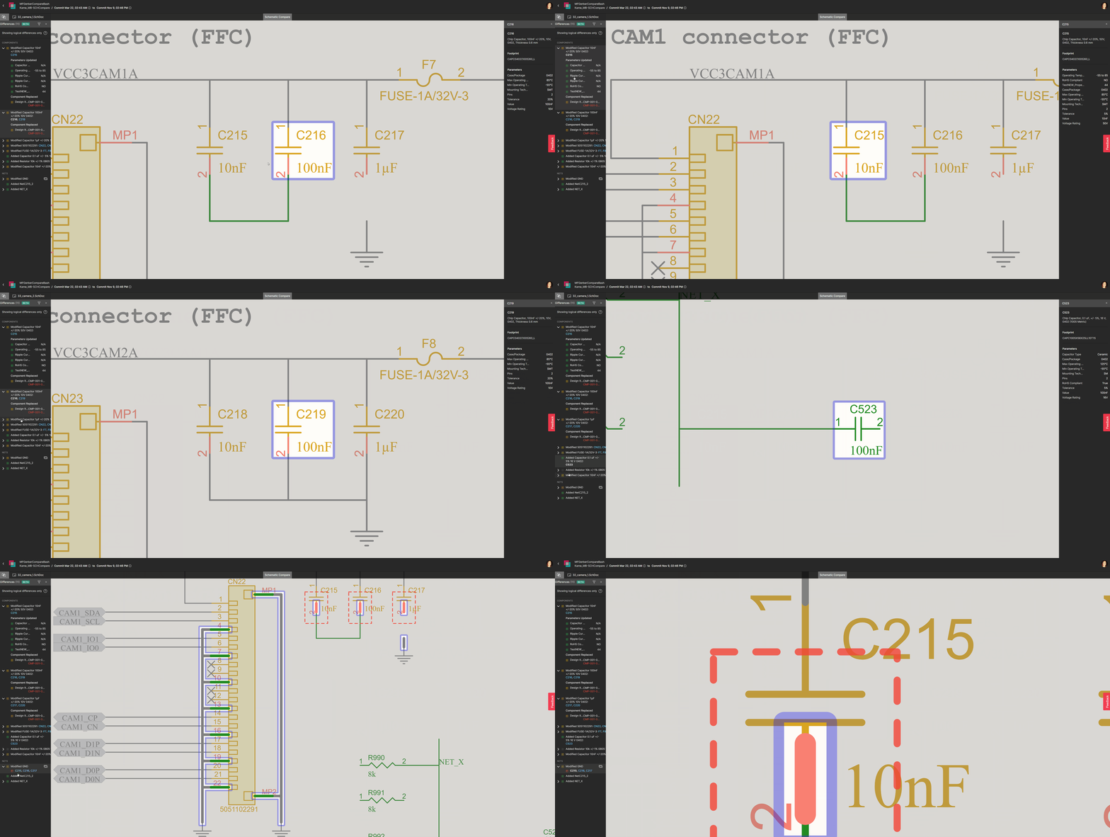
Schematic Compare only shows logical differences; the graphical changes are not displayed (such as moving a symbol on a sheet or changing a text string).
2. Easy navigation
The Differences panel on the left-hand side shows the differences in the Components or the Nets between the two selected commits or releases. The differences detected in the board design are listed in the Differences Panel. You can cross probe to the latest version of the schematic/layout, where these differences are color coded and highlighted:

You can select a component in the Differences panel to view its properties. The component’s properties shown refer to the latest schematic.
3. Elements can be found by name in the search bar
If you are looking for a specific element, you can type its name in the search bar (shown below):

4. Detailed change track
The list on the left displays all parameters of the selected element, comparing the old and new parts. In this way, you do not need to search for the data inside the schematics to see which parameters have changed or which nets have been added or removed; do this quickly in an overview in Schematics Compare to save time.

You can find more information on using Schematic Compare in Altium 365 by visiting the Getting Started Guide - Schematic Compare.
The history of changes is shown in MCAD CoDesigner's panel, making the interaction between the electrical and mechanical engineers more transparent. As soon as changes are applied/rejected on one side, the engineer on the other side is notified, and any rejection comments are displayed.
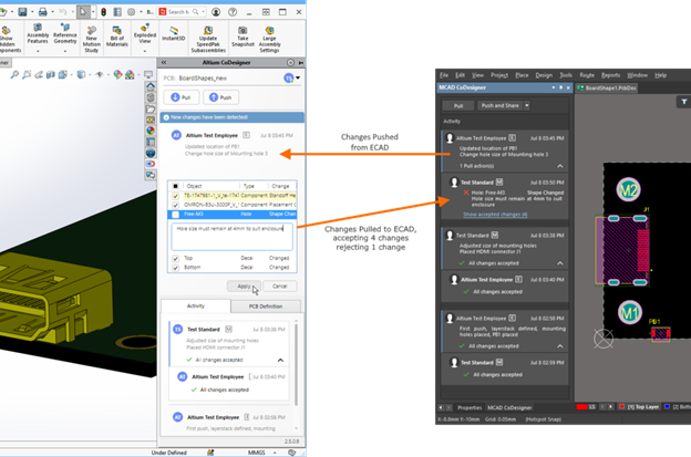

Please access our online documentation for detailed information on the feature: Support for Change History and Rejection Comments.
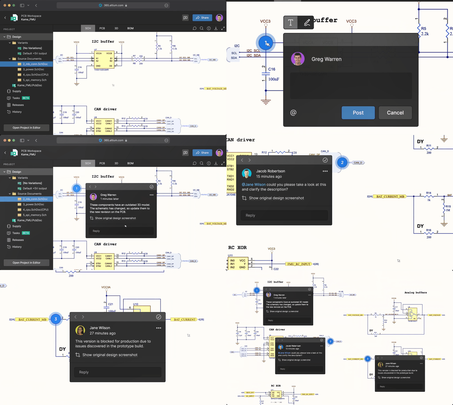
How is it useful?
- Different users can collaborate in real-time, in a chat-like, conversational format.
- Specific contextual annotations on your design can be collected.
- Conversations are never lost or misplaced since everything is tracked through Altium 365 and backed up in the cloud.
- Notifications allow users to stay engaged even if they are not actively working with a design.
- People outside of your Workspace team—invited by you—can view and leave any comments via a web-based application without an Altium Designer License.
Here's what to expect:
Collaboration in Real-Time through the Comments Panel
Like a news feed, the comments panel on the right-hand side displays comments chronologically, and you, as a team member, can efficiently manage these comments in one place:
- Place a Comment: Places a comment on any object or area of your design.
- Filter Comments: Shows only the comments that match your specified criteria. You can filter comments by status (resolved or unresolved) and by a particular user.
- View Comments: Shows a list of all responses and comments received for your design, with recent comments at the top.
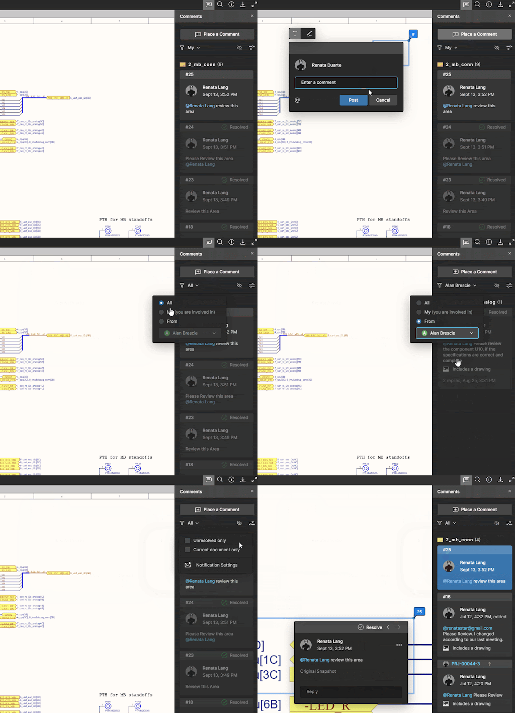
Use Drawing Markup Tools to Add Comments
- The markup is graphically drawn with a pen tool at the top of the comment dialog box.
- You can specify the line width, color, and other properties before you draw.
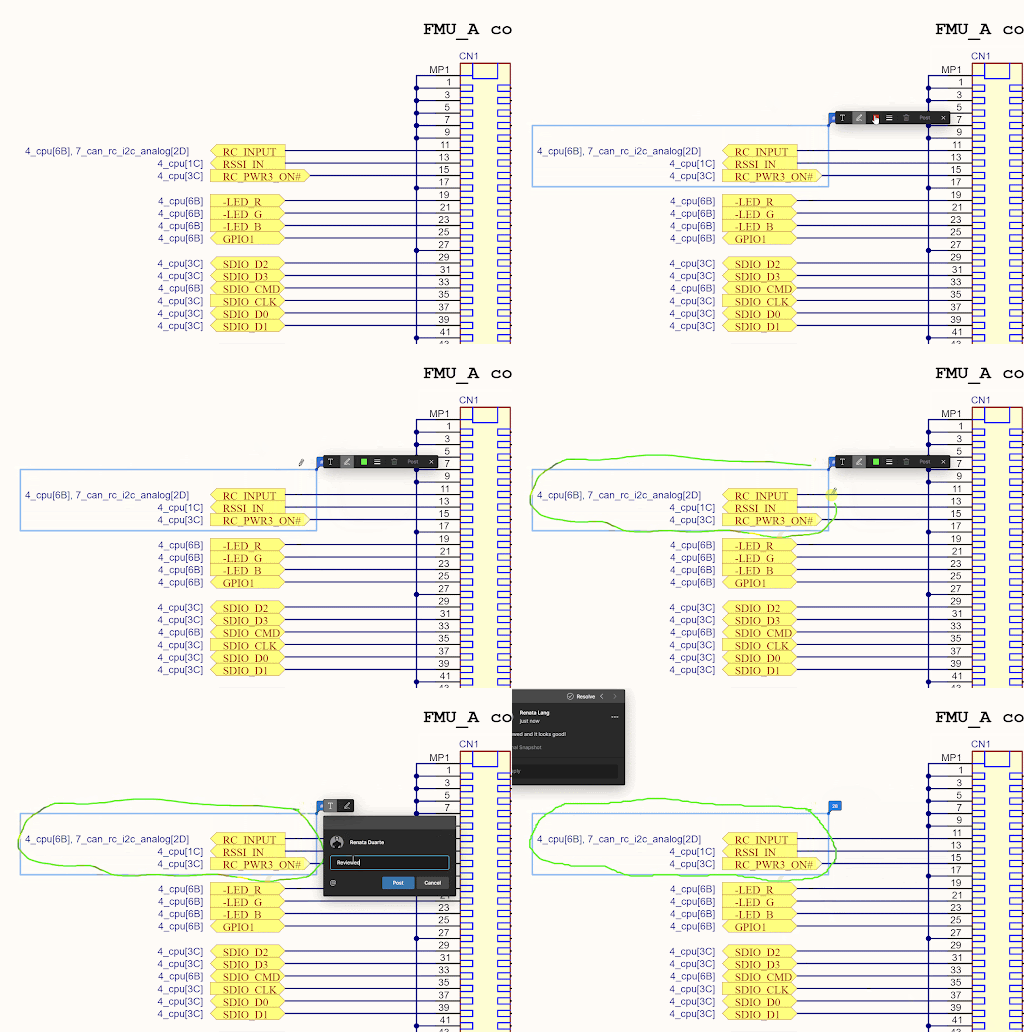
After starting a new comment or reply, you can use the @mention feature to notify one or more members of your organization. Just type the @ symbol followed by the name of the user or email.
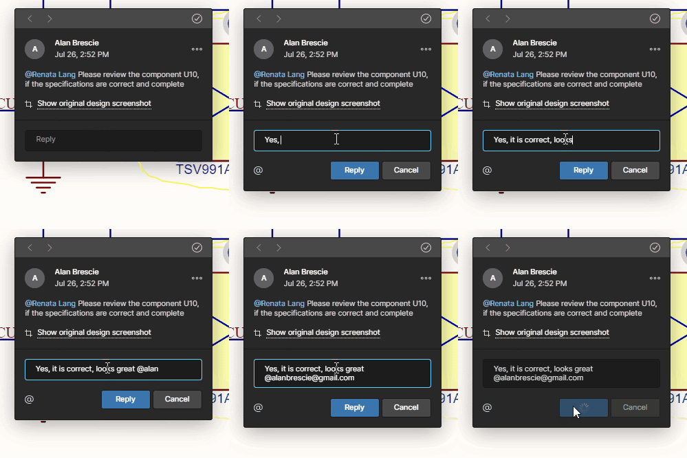
When you post your comment, the person you @mentioned will receive an email notification. Anyone who started the comment thread will also be notified. Notification emails let your colleagues know that there's been new activity in the comment thread and that you have left a comment. They can reply to your comment or click a link in the notification email to open the document and go straight to the comment in its context.
Please note that comments or replies can only be edited by the person who created them.
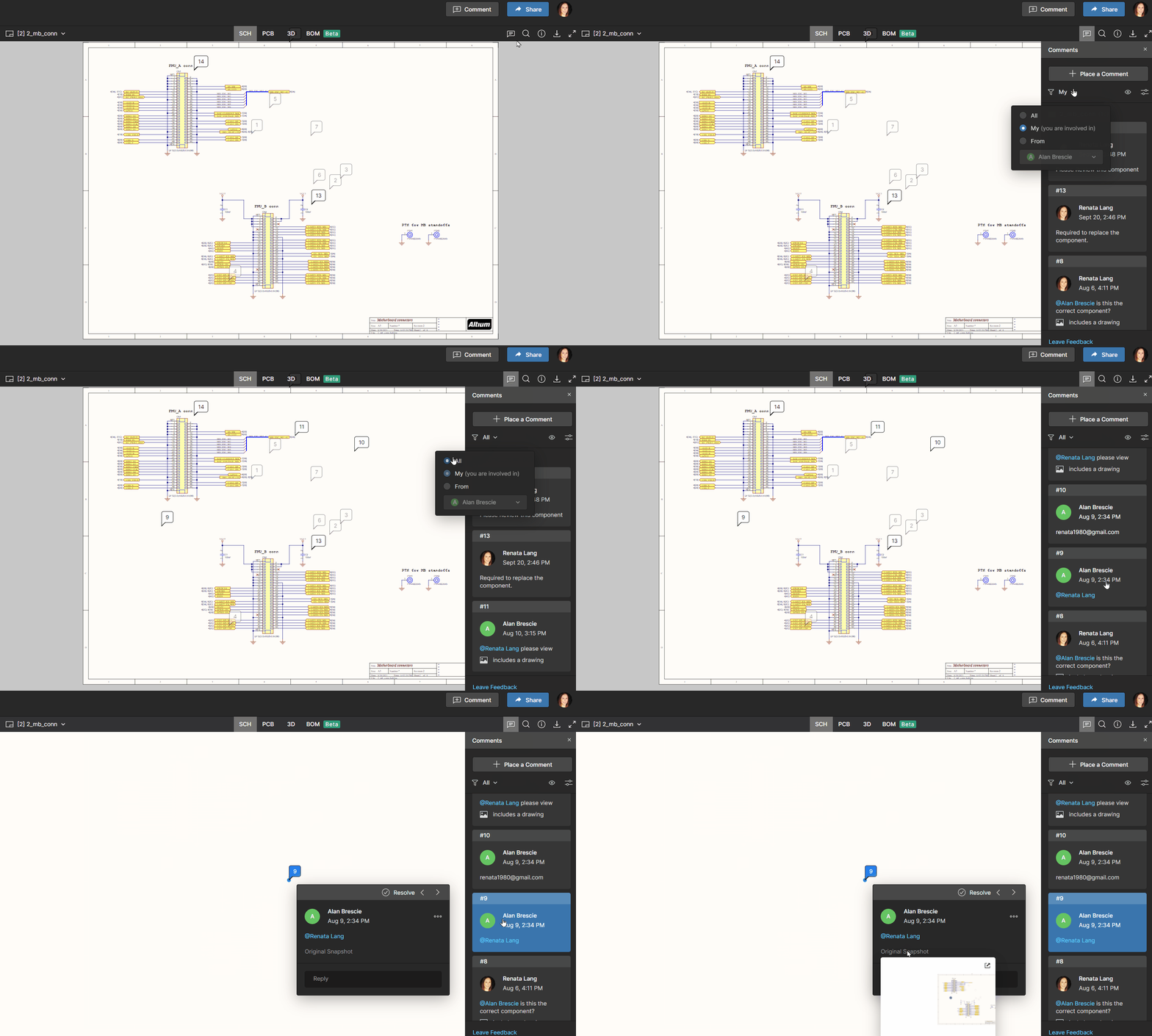
In the Comments panel, comments are side-by-side with the page content to help you focus on the most relevant feedback for the part of the document you’re working on. You can see a single list of all comments in your document, including resolved comments. To turn the Comments panel on and off, simply click the Comments button in the upper-right corner of your window.
Resolve a Comment Thread
Comments in documents generally represent questions, ideas, or concerns about the project. When those have been addressed, comments allow you to mark that thread as resolved. Resolved comment threads can appear in the side view, but you can choose to show unresolved comments only.
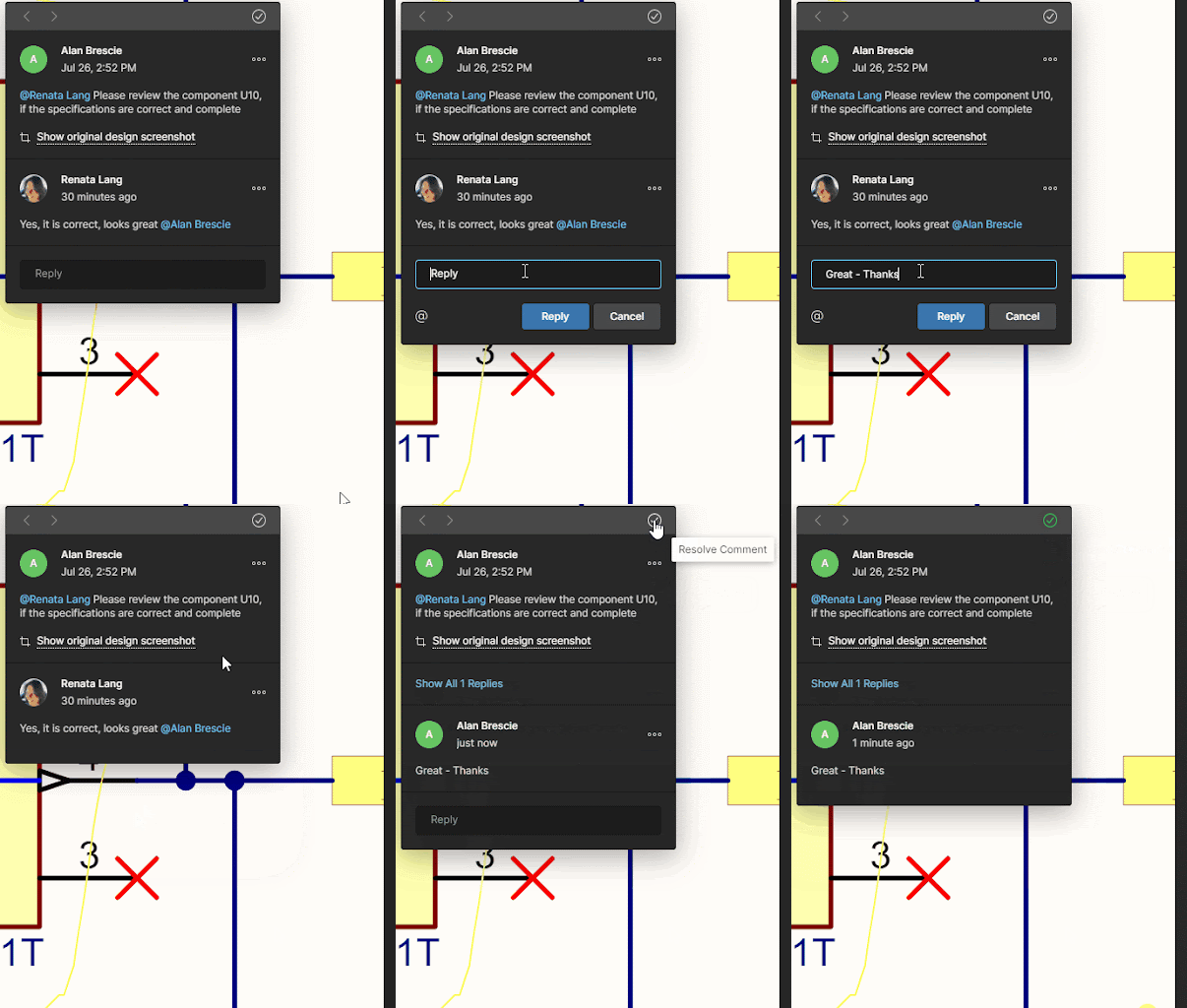
Notification Settings – you can choose to receive email alerts for all comment activity, for only those comments where you are mentioned or assigned, or not receive email alerts at all.
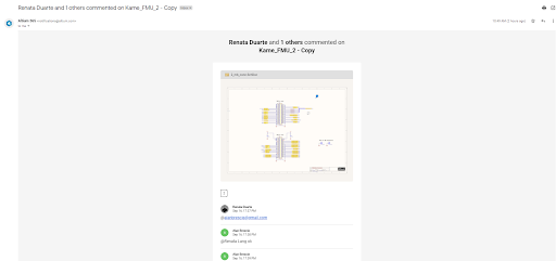

Please access our online documentation for detailed information on this feature: Working with Altium 365 - Commenting in Your Design.
Project History in a Nutshell
- Presents events as a chronological timeline (Creation, Commits, Releases, Clones, and MCAD Exchanges)
- Auto-generates Differences Summary to view the differing entities (e.g., replaced components)
- Even a non-expert can act on a revision (Download, View, Revert)
Version Control and Chronological Timeline
We are introducing a new feature for tracking the history throughout the project— Project History. When you click the History in the sidebar, you can scroll down quickly to see the entire timeline, as well as details about significant events: (Who, What, When, Why, and How).
Text search in Local History revisions
You can quickly find components by typing the query in the search bar in the upper right-hand corner of the screen.
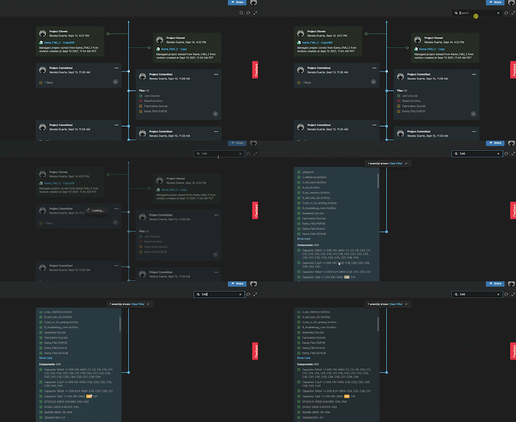
Embedded Compare Function
The Project History feature includes an embedded compare function that shows the differences between two versions of Schematics, BOM, or Gerber files - you can compare between commits or releases.

Clone a Project
This operation lets you create a new project without having to configure them from scratch. Once you create the new project, you can modify its settings independently from the original project. You can also choose which folder you want to save the cloned project.
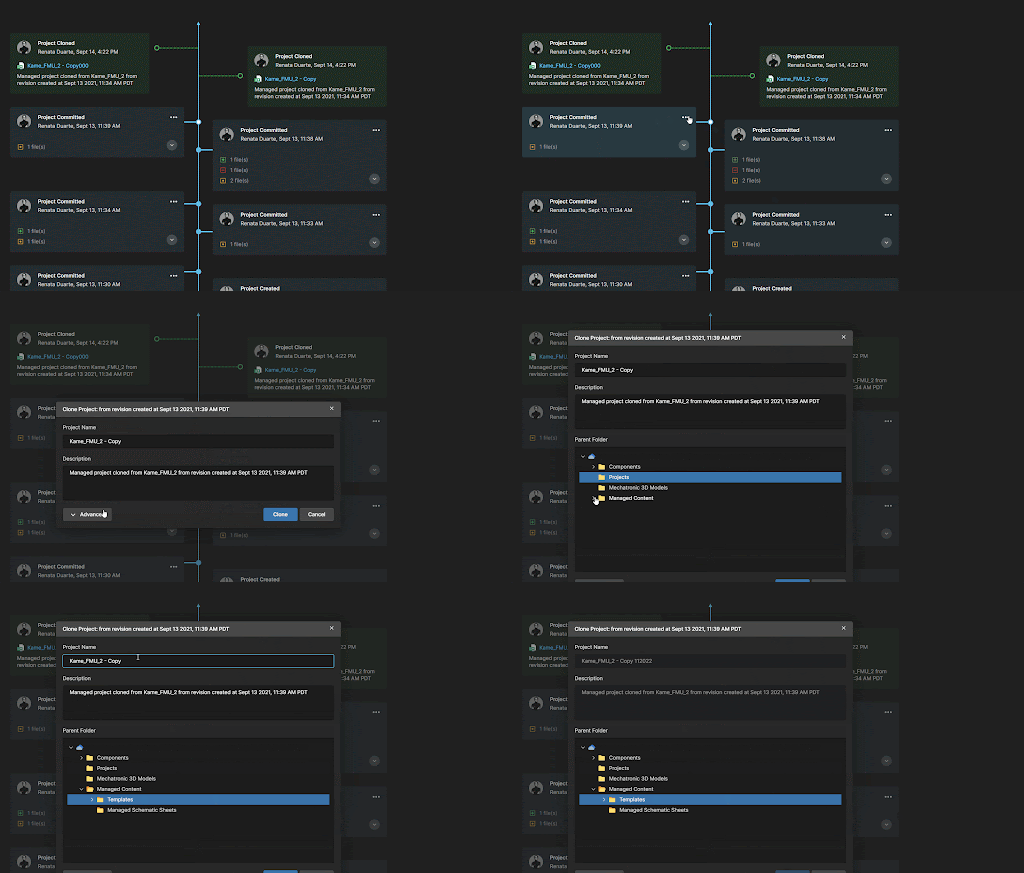
Download Previous Commits or Releases
It’s easy to navigate back to your project history, view past versions of documents and revert to previous versions if needed. Download the complete project or only the snapshot copy in a fast way.
To access the Project History, follow these simple steps:
1. Access the Altium 365 workspace
2. Go to Projects and open the project to which you want to see the history of the activity.
3. Click on the History tab on the left side pane.
4. Scroll through the screen to see all releases and commits since the creation of the project.

Please access our online documentation for detailed information on the feature: Project History in an Altium 365 Workspace.
What’s New
Webinar


